
Boot attachment method and constant velocity universal joint

Active Publication Date: 2018-02-15
NTN CORP
View PDF7 Cites 0 Cited by
  • Summary
  • Abstract
  • Description
  • Claims
  • Application Information

AI Technical Summary

Benefits of technology

The present invention relates to a high-frequency induction heating device used in various industrial applications. The technical effects of the invention include maintaining an accurate gap between the heated object and the high-frequency induction heating coil, resulting in uniform adhesive strength and stable joining strength, without the need for relative movement between the mating member and the coil. The use of heat-insulating materials and a labyrinth structure further contribute to the stable joining strength and prevent contamination and leakage of sealed joints. Additionally, the invention reduces the size and cost of the high-frequency induction heating device due to the absence of relative movement between the mating member and the high-frequency induction heating coil.

Problems solved by technology

As a result, manufacture cost required for assembly of the constant velocity universal joint is increased.
However, there is difficulty in achieving highly accurate fastening while dealing with variation in individuals.

Method used


Image

  • Boot attachment method and constant velocity universal joint
  • Boot attachment method and constant velocity universal joint
  • Boot attachment method and constant velocity universal joint

Examples


example 1

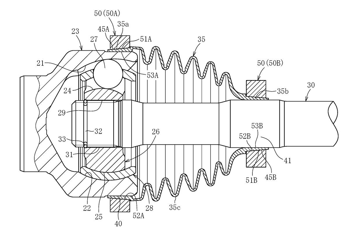
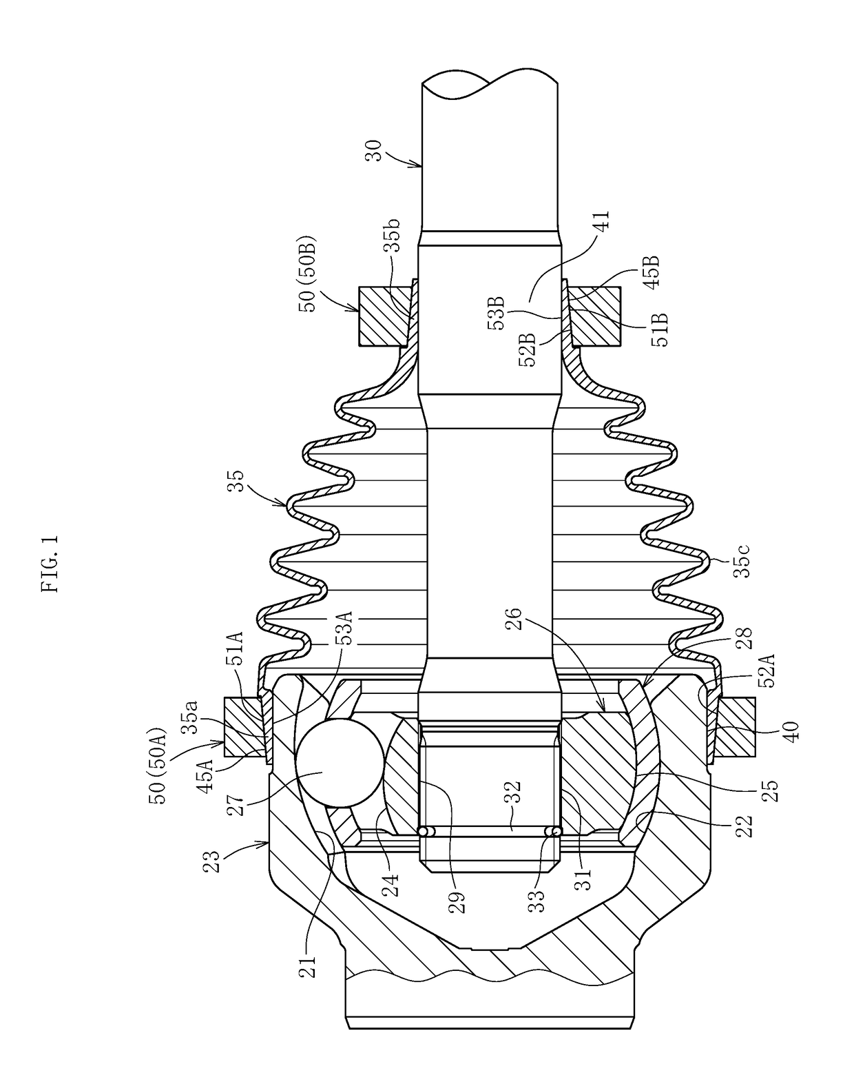
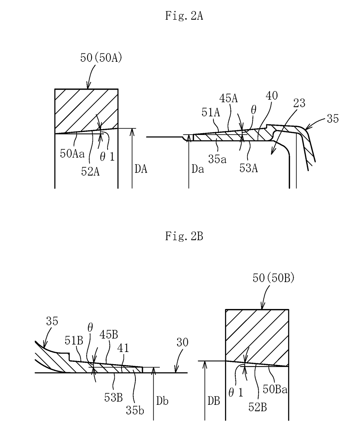
[0182]The interference between the boot end portion and the shaft was changed, and the ease of mounting of the boot and the joining strength for each interference were studied. The results are shown in the following Table 1 and Table 2. Table 1 and Table 2 are record tables with regard to an interference between an inner diameter (diameter) of the boot end portion and an outer diameter (diameter) of the receiving surface of the mating member. In Table 1, connection between the boot end portion (mounting portion) 35b and the shaft 30 is shown, in a case in which an inner diameter dimension of the boot end portion (mounting portion) 35b is 22 mm (diameter). In Table 2, connection between the boot end portion (mounting portion) 35a and the outer joint member (outer ring) 23 is shown, in a case in which an inner diameter dimension of the boot end portion (mounting portion) 35a is 70 mm (diameter). In Table 1 and Table 2, the comprehensive evaluation of “excellent” is denoted by CD. The ...

example 2

[0184]A grease leakage test was conducted for the boot having the boot end portion mounted and fixed to the shaft through use of coils having different shapes of the mating surface. Results thereof are shown in the following Table 3. For this test, the fixed type constant velocity universal joint illustrated in FIG. 5 was used, and a swing angle of from 25 degrees to 40 degrees and the rotation speed of 500 rpm were set.

TABLE 3StraightLabyrinth 1Labyrinth 2Coil Mating SurfaceGrease Leakage Test50 hours70 hours85 hours

[0185]According to the results, the straight mating surface having no stepped structure caused leakage after 50 hours. The labyrinth 1 (stepped structure illustrated in FIG. 7) did not cause leakage after operation for 70 hours. The labyrinth 2 (stepped structure illustrated in FIG. 12) did not cause leakage after operation for 85 hours.


PUM

PropertyMeasurementUnit
Angleaaaaaaaaaa
Angleaaaaaaaaaa
Lengthaaaaaaaaaa

Abstract

Provided is a boot mounting method for a constant velocity universal joint in which a boot end portion is mounted and fixed to a mating member made of metal. After the boot end portion is fitted over a receiving surface being a radially outer surface of the mating member, a high-frequency induction heating coil having a ring shape is fitted over the boot end portion. Only a top portion of the receiving surface of the mating member is heated by high-frequency induction through application of a high-frequency current to the high-frequency induction heating coil. With this action, a mounting surface being a radially inner surface of the boot end portion and the receiving surface being the radially outer surface of the mating member are integrally joined to each other.

Description

TECHNICAL FIELD[0001]The present invention relates to a boot mounting method for a constant velocity universal joint, and to a constant velocity universal joint which is constructed using the boot mounting method.BACKGROUND ART[0002]For a constant velocity universal joint which is to be assembled to, for example, a power transmission mechanism of automobiles and various industrial machines, a boot (boot for a constant velocity universal joint) is mounted for the purpose of preventing entry of foreign matters such as dust into the joint and preventing leakage of grease sealed in the joint.[0003]As illustrated in FIG. 28, a constant velocity universal joint (fixed type constant velocity universal joint) includes an outer joint member 3, an inner joint member 6, a plurality of balls 7, and a cage 8. The outer joint member 3 has a plurality of track grooves 1, which are formed in a radially inner surface 2 and extend in an axial direction. The inner joint member 6 has a plurality of tra...

Claims


Application Information

Patent Timeline
IPC IPC(8): F16D3/84B29C65/00B29C65/32
CPCF16D3/845B29C65/32B29C66/742F16D2250/0084B29K2667/00F16J3/042F16D2003/22316F16J15/52F16D3/84F16J3/04
Inventor KOHARA, MIKA
Owner NTN CORP
Learn More