Lubricating apparatus of vehicle

a technology of lubricating apparatus and vehicle, which is applied in mechanical apparatus, gearing details, transportation and packaging, etc., can solve the problems of insufficient supply of lubricating oil from the first oil pump, and high oil pressure of the supply passage, etc. cost

Active Publication Date: 2018-02-15
TOYOTA JIDOSHA KK
View PDF1 Cites 27 Cited by
  • Summary
  • Abstract
  • Description
  • Claims
  • Application Information

AI Technical Summary

Benefits of technology

[0010]According to the first aspect, since the first supply passage connected to the first oil pump and the second supply passage connected to the second oil pump are independently provided so as to supply the lubricating oil to the common lubricated parts, even during the low speed traveling in which the rotational speed of the first oil pump rotary-driven in accordance with the vehicle velocity is slow, it is possible to supply the lubricating oil to the common lubricated parts separately from both the first and second oil pumps via the respective different supply passages. Accordingly, even during the low speed traveling with a high load in which a requested drive force is great, it is possible to supply a sufficient amount of lubricating oil to the predetermined lubricated parts from both the first oil pump and the second oil pump, and properly lubricate these lubricated parts.
[0011]The second aspect relates to a hybrid vehicle including the EV travel mode and the HV travel mode, and is the case in which the second oil pump is an oil pump mechanically rotary-driven along with the rotation of the engine; and during the traveling in the EV travel mode with a low load, the lubricating oil is supplied by the first oil pump; and on the o...

Problems solved by technology

When a large amount of lubricating oil is supplied from the second oil pump, the oil pressure of the supply passage becomes too high, so that the lubricating oil cannot be supplied from the first oil pump.
Consequently, only the lubricating oil discharged from the second oil pump can substantially be supplied, so t...

Method used


Image

  • Lubricating apparatus of vehicle
  • Lubricating apparatus of vehicle
  • Lubricating apparatus of vehicle

Examples


Embodiment Construction

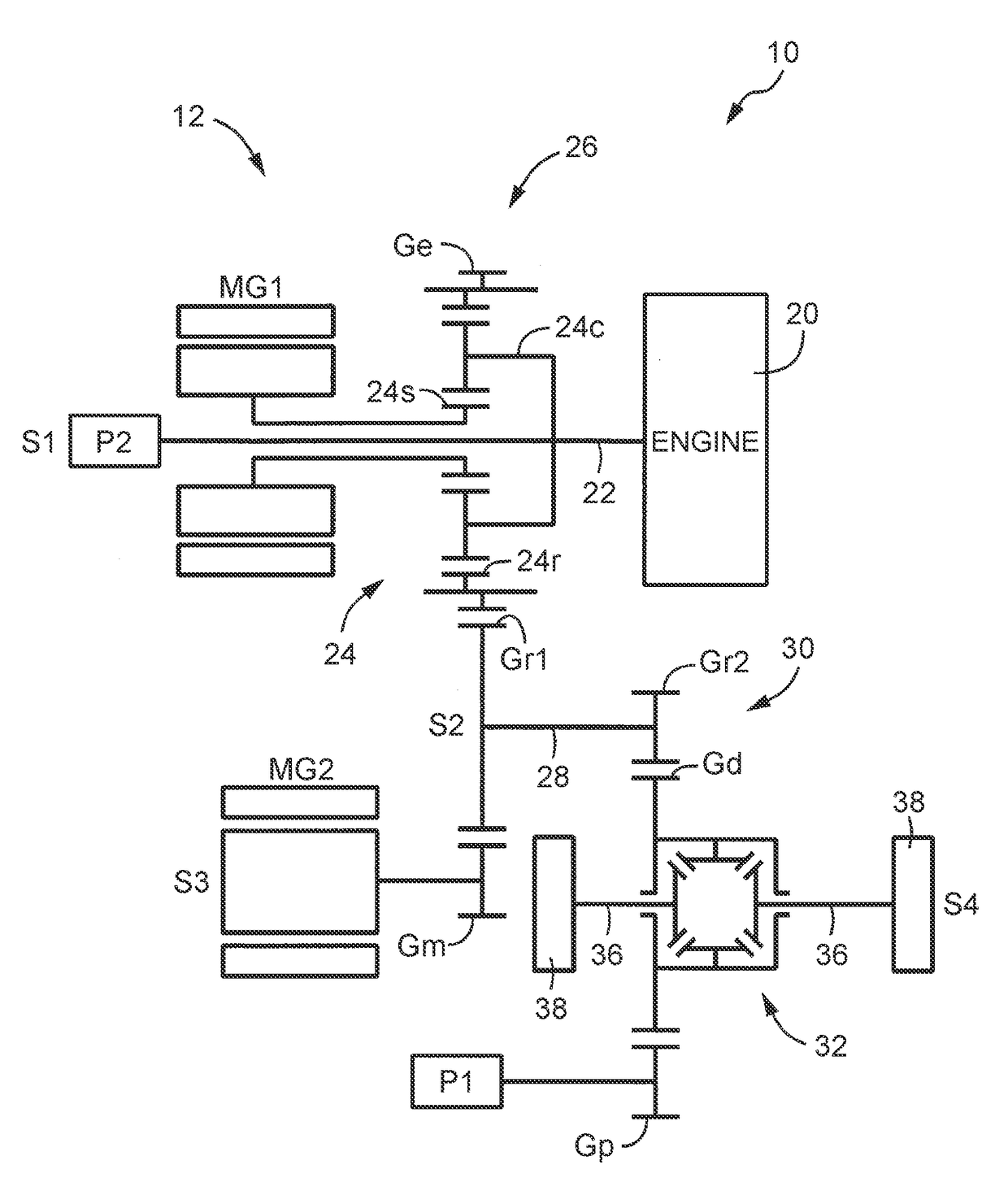
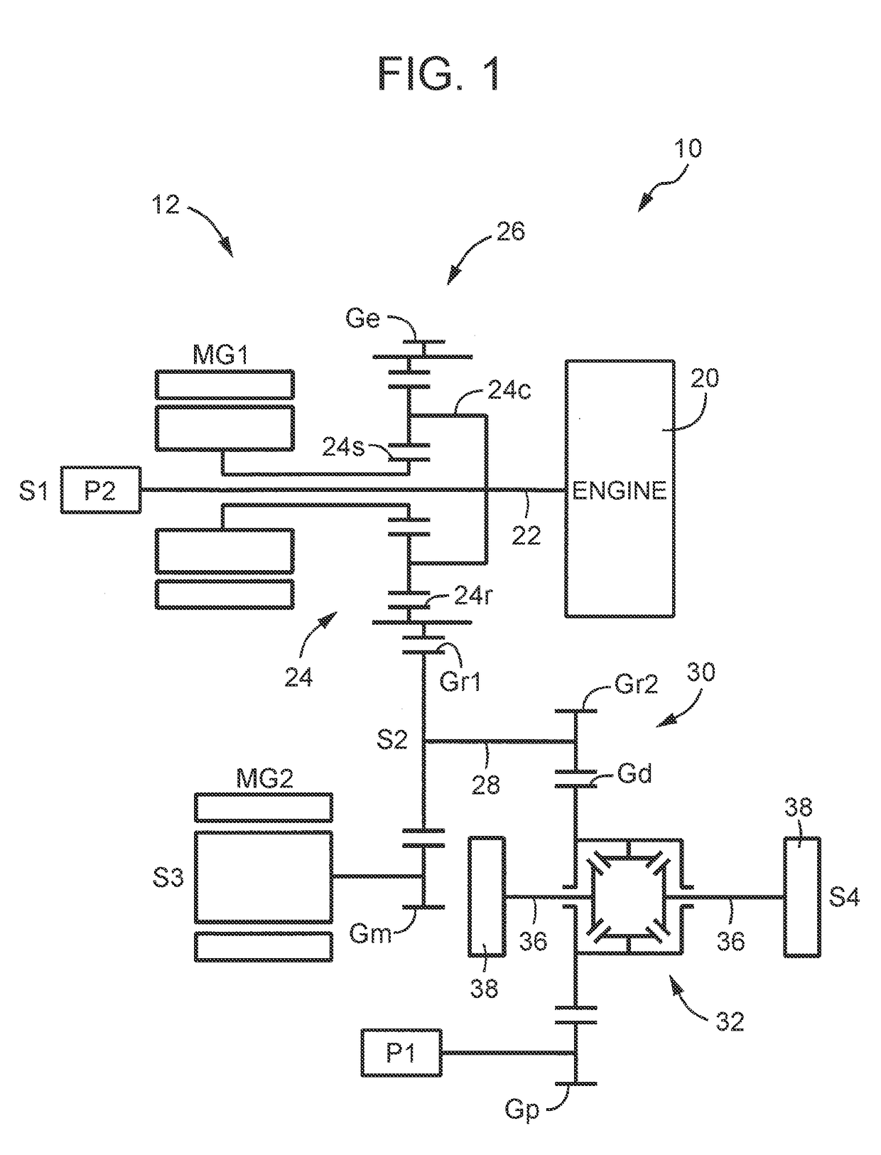
[0023]The present disclosure is preferably applied to an engine drive vehicle, a hybrid vehicle including a rotary machine for travel in addition to an engine as a drive source for travel, and others; but the present disclosure can also be applied to an electric vehicle or the like equipped with only an electric motor as a drive source. As the rotary machine for travel, it is proper to use a motor generator that can alternatively use functions of an electric motor and an electric power generator, for example, but an electric motor may also be used. As the power transmission system, a horizontal type transaxle such as an FF (front engine-front drive) transaxle having multiple shafts arranged in the vehicle width direction may preferably be used, but an FR type or a four-wheel drive type power transmission system may also be used.

[0024]An output unit of the power transmission system driving the first oil pump is a differential unit or the like that distributes a drive force transmitte...


PUM


Abstract

A lubricating apparatus for a vehicle, comprises a first oil pump and a second oil pump, and a first supply passage connected to a discharge side of the first oil pump on which the lubricating oil is discharged so as to supply the lubricating oil discharged from the first oil pump to lubricated parts of the power transmission system, a second supply passage that is provided independently from the first supply passage and is connected to a discharge side of the second oil pump on which the lubricating oil is discharged so as to supply the lubricating oil discharged from the second oil pump to the lubricated parts of the power transmission system.

Description

INCORPORATION BY REFERENCE[0001]The disclosure of Japanese Patent Application No. 2016-159009 filed on Aug. 12, 2016 including the specification, drawings and abstract is incorporated herein by reference in its entirety.BACKGROUND[0002]1. Technical Field[0003]The technical field relates to a lubricating apparatus of a vehicle, and particularly to a lubricating apparatus capable of properly supplying a lubricating oil even when the vehicle travels at low speed.[0004]2. Description of Related Art[0005]There has been proposed a lubricating apparatus applied to (a) a vehicle including a power transmission system to transmit a drive force from a drive source via an output unit to driven wheels, and the lubricating apparatus includes: (b) a first oil pump mechanically rotary-driven along with rotation of the output unit; and a second oil pump rotary-driven by a rotary drive source different from the output unit, wherein the lubricating apparatus is configured to supply the lubricating oil...

Claims


Application Information

Patent Timeline
IPC IPC(8): F16H57/04
CPCF16H57/0439F16H57/0424B60K6/20F16H57/045F16H57/0427F16H57/0435F16H57/0441F16H57/0453B60K6/445Y02T10/62
Inventor KIYOKAMI, HIROAKINISHIKAWA, YUKINOBUHORI, TETSUOOKUNO, HAKUBA
Owner TOYOTA JIDOSHA KK
Why Eureka
Try Eureka