Rear facing multi-light and function light bar

a multi-function, rear-facing technology, applied in fixed installation, light source semiconductor devices, lighting and heating apparatus, etc., can solve the problems of high cost, large size, and large difficulty in achieving a fully sealed light, and achieve the effect of reducing tooling and assembly cos

Active Publication Date: 2018-02-15
BESTOP BAJA LLC
View PDF11 Cites 8 Cited by
  • Summary
  • Abstract
  • Description
  • Claims
  • Application Information

AI Technical Summary

Benefits of technology

[0006]The present invention is directed to a rear facing light bar assembly that incorporates a taillight, brake light, amber warning light and a backup light (or blue light for racers) in a small integrated unit. The light is constructed such that the electronics are completely protected...

Problems solved by technology

The problem with this approach is that the light becomes very expensive, nearly equal to that of the forward projecting light bar, heavy and much larger in size than it needs to be.
In addition, a forward projecting light requires individual optics, lenses and bezels so achieving a fully sealed light becomes much more difficult and expensive with the need of custom molded O-rings and careful assembly of the light.
The custom seals are a big disadvantage when trying to produce an inexpen...

Method used


Image

  • Rear facing multi-light and function light bar
  • Rear facing multi-light and function light bar
  • Rear facing multi-light and function light bar

Examples


Embodiment Construction

[0028]The following description of the preferred embodiment(s) is merely exemplary in nature and is in no way intended to limit the invention, its application, or uses.

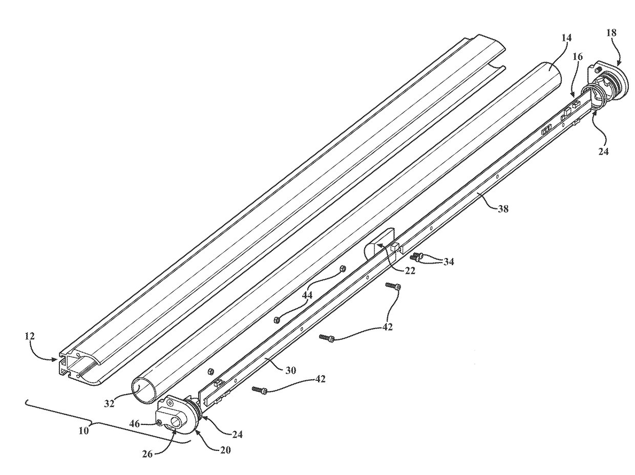
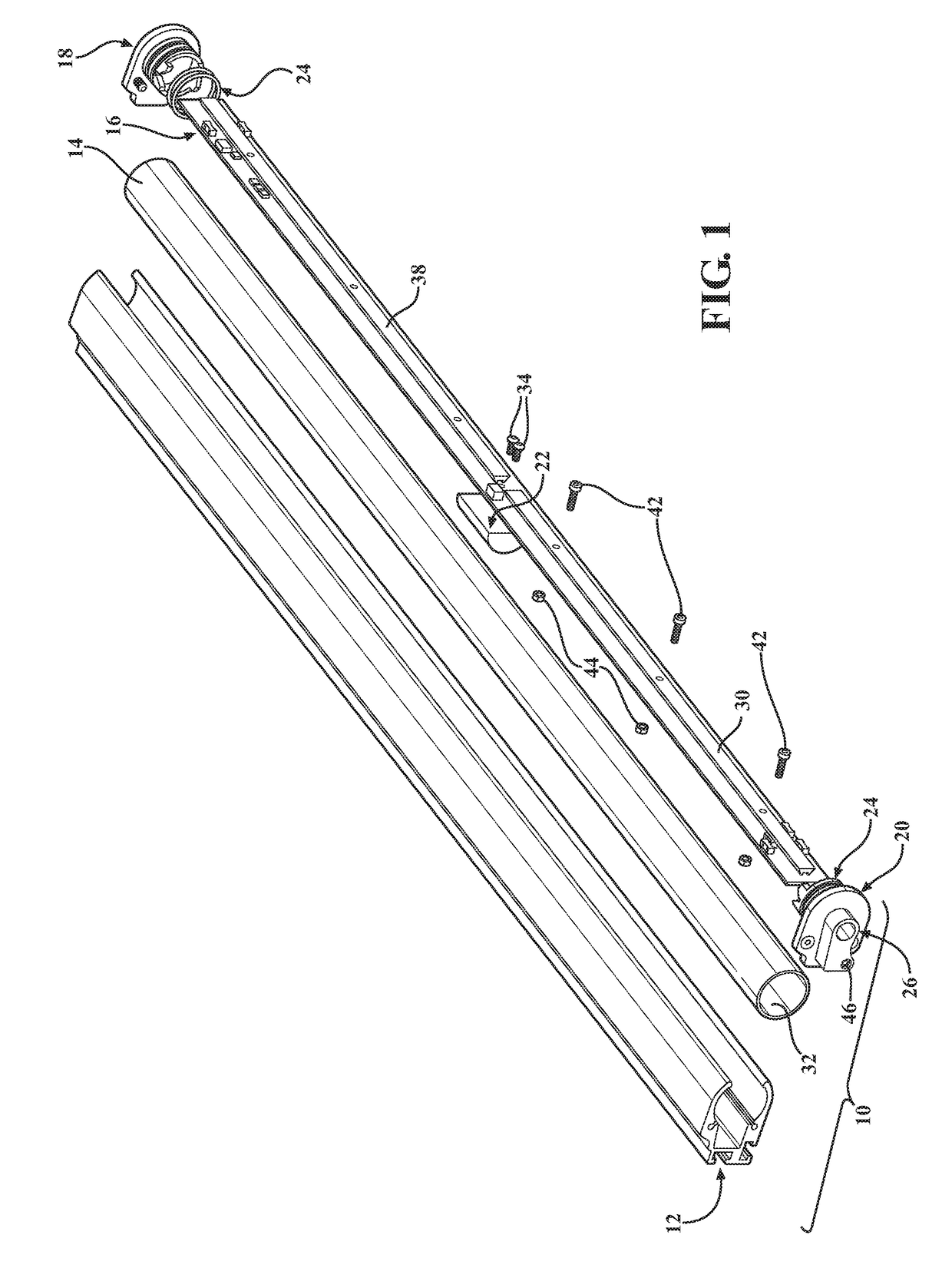
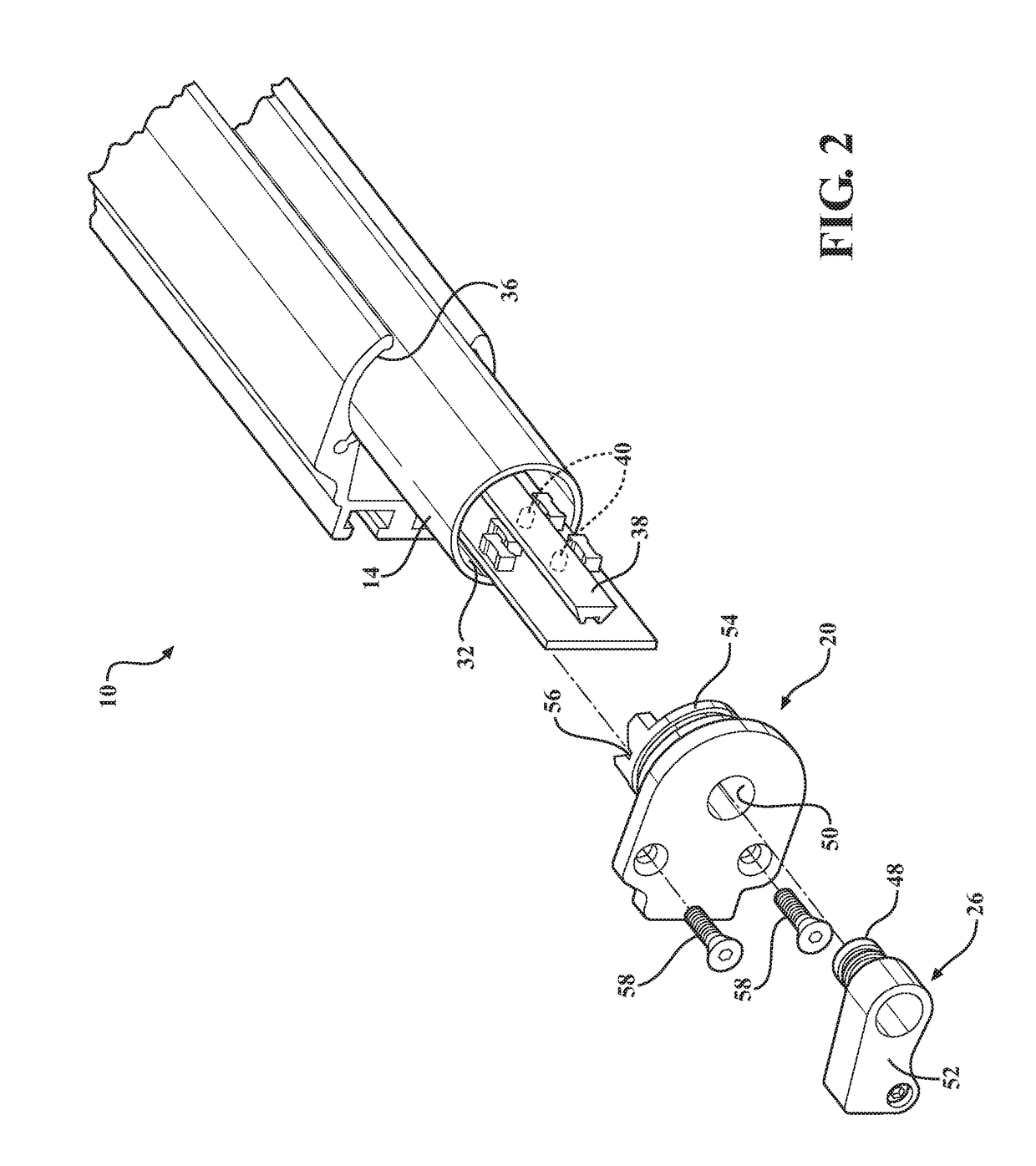
[0029]Referring to the figures generally, the present invention provides a rear facing light bar assembly 10 (or “assembly”) that provides integrated brake light and tail light functioning off the same LEDs. The assembly 10 includes a compact four wire cord to power all board functions. A ¾ pressure extruded housing holds the light and provides mounting functions for the user. A scalloped extrusion profile of the housing holds a polycarbonate tube of the light in place. Two continuous optics are shared by multiple LED's.

[0030]Referring to FIGS. 1-8 generally, there are many different components that go into making the assembly 10. The primary components include at least the following: at least one extruded housing shown generally at 12, at least one polycarbonate tube lens 14, dual circuit board assembly shown general...


PUM


Abstract

A rear facing light bar assembly that incorporates a plurality of light functions in a small integrated unit. A multifunctional circuit board powers different colored light emitting diodes to produce the tail light, brake light, amber and/or backup light. The assembly also has end caps, a one-piece polycarbonate tube lens and an extruded housing. Heat from the circuit board is dissipated through the end caps and into the extruded housing. The assembly is constructed such that the electronics are completely protected from the outside environment, and sealed from water and dust intrusion. The light also minimizes tooling and assembly cost, yet provides a secure seal protecting the electrical components. In addition, the light is serviceable so individual parts can be replaced or repaired if parts are damaged.

Description

CROSS-REFERENCE TO RELATED APPLICATIONS[0001]This application claims the benefit of U.S. Provisional Application No. 62 / 373,125, Filed Aug. 10, 2016. The disclosures of the above application are incorporated herein by reference.FIELD OF THE INVENTION[0002]The present invention relates to a rear facing light bar for mounting to a vehicle, such as a racing vehicle.BACKGROUND OF THE INVENTION[0003]Known attempts to create a rear facing light bar includes taking larger forward projecting light bars and replacing the circuit board with one that provides the functions of a tail light, brake light, warning light and back up light. The problem with this approach is that the light becomes very expensive, nearly equal to that of the forward projecting light bar, heavy and much larger in size than it needs to be. In addition, a forward projecting light requires individual optics, lenses and bezels so achieving a fully sealed light becomes much more difficult and expensive with the need of cust...

Claims


Application Information

Patent Timeline
IPC IPC(8): F21S4/28F21S8/10B60Q1/30
CPCF21S4/28F21Y2103/10F21S48/215B60Q1/30F21V29/70F21S10/023F21V5/04F21V15/02F21V23/004F21Y2115/10B60Q1/2607B60Q1/2696F21S43/19F21S43/15F21S43/27F21S43/26F21S43/14
Inventor ROACH, ALAN R.JOHNSON, CHRISTOPHER C.
Owner BESTOP BAJA LLC
Why Eureka
Try Eureka