
Image processing apparatus, method, and program

Active Publication Date: 2018-03-01
FUJIFILM CORP
View PDF0 Cites 3 Cited by
  • Summary
  • Abstract
  • Description
  • Claims
  • Application Information

AI Technical Summary

Benefits of technology

The patent describes a method to reduce the amount of artifacts in tomographic images. These artifacts can be caused by the process of generating the image, and can make the image appear less accurate. The method described in this patent involves using a series of band tomographic images and weighting them based on their frequency to create a composite two-dimensional image. This method reduces the impact of artifacts and creates an image that looks closer to a traditional two-dimensional image. Compared to other methods, this method is more efficient and accurate, especially when dealing with relatively thick structures.

Problems solved by technology

Therefore, it is possible to find a lesion that has been difficult to detect in a two-dimensional image acquired by simple imaging in the related art.
On the other hand, the tomosynthesis imaging has a problem that a reconstructed tomographic image is blurred due to the mechanical error of the imaging apparatus and the influence of body motion of the subject due to the time difference of imaging at each of a plurality of radiation source positions.
However, when both tomosynthesis imaging and simple imaging are performed, the exposure dose to the subject increases.
Incidentally, in the tomosynthesis imaging, the incidence angle when irradiating the subject is limited.
As a result, it is difficult to check a structure required for diagnosis of a lesion or the like.
This is a problem similarly occurring in the case of generating a composite two-dimensional image using the minimum value projection method disclosed in JP2014-133095A.

Method used


Image

  • Image processing apparatus, method, and program
  • Image processing apparatus, method, and program
  • Image processing apparatus, method, and program

Examples


first embodiment

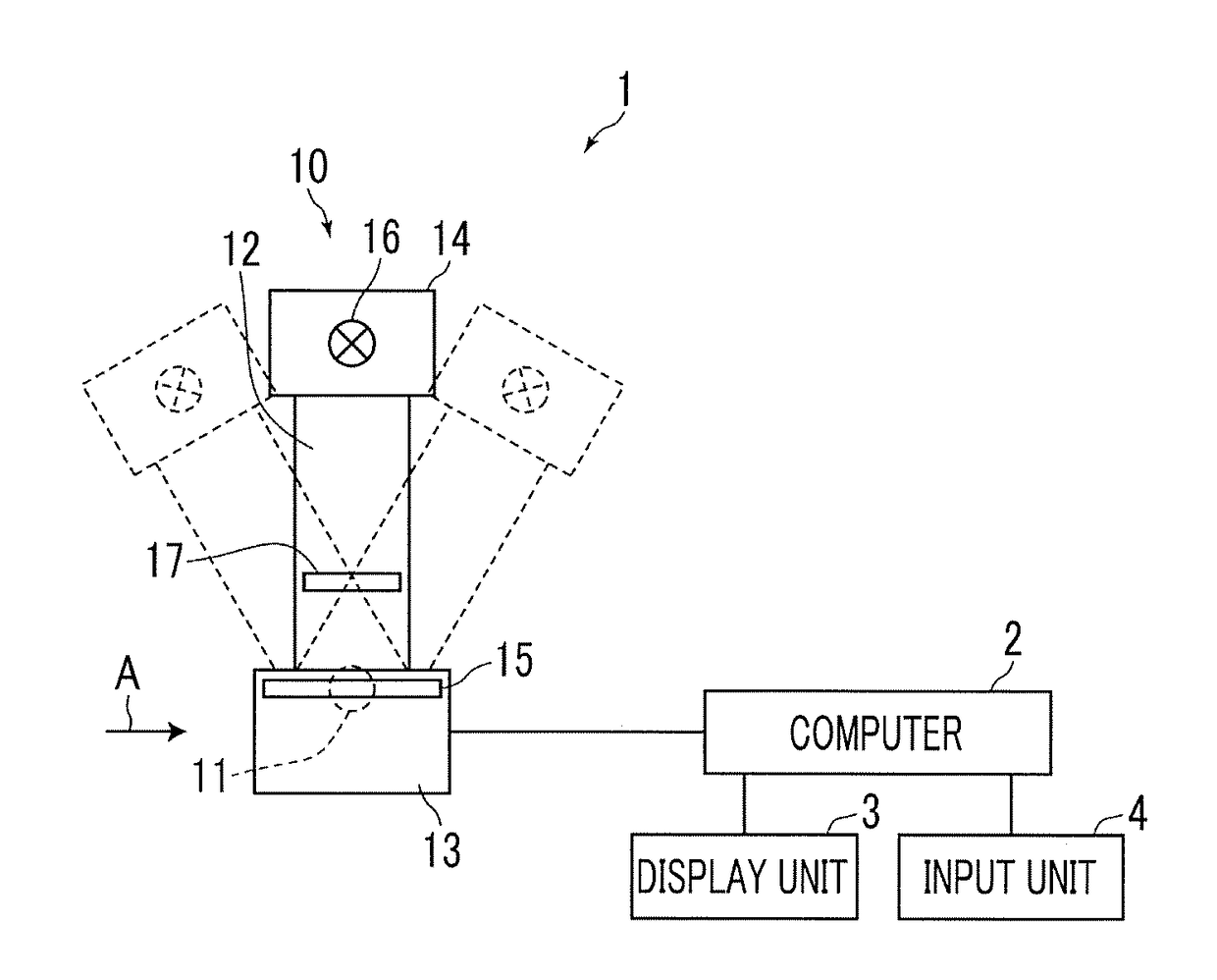
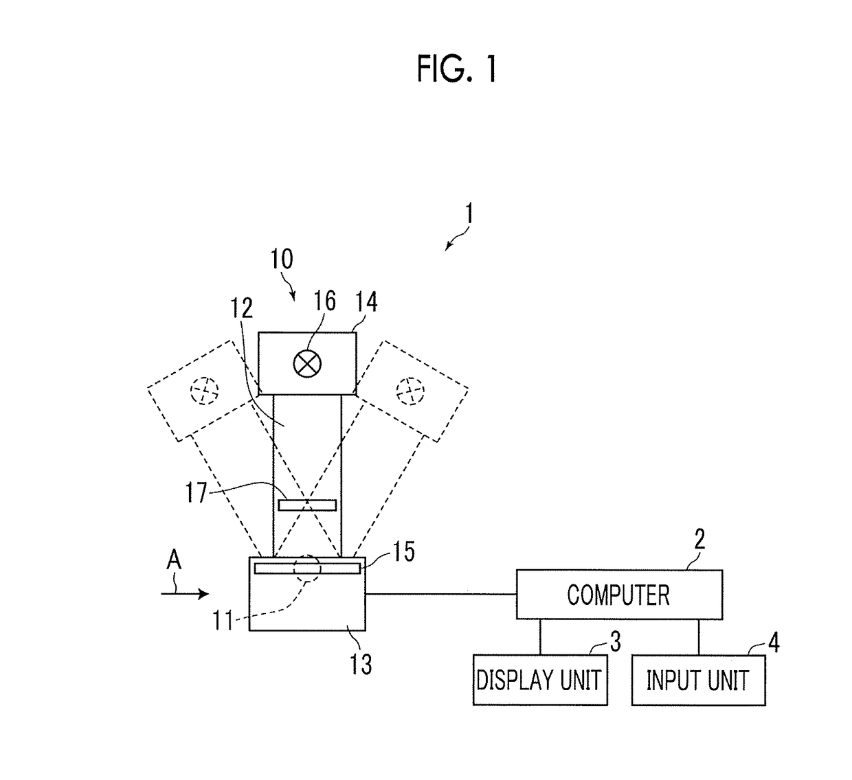
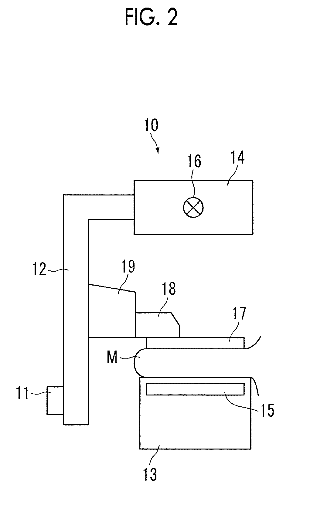
[0063]Hereinafter, embodiments of the invention will be described with reference to the accompanying diagrams. FIG. 1 is a schematic configuration diagram of a radiation image capturing apparatus to which an image processing apparatus according to the invention is applied, and FIG. 2 is a diagram of the radiation image capturing apparatus when viewed from the direction of arrow A in FIG. 1. A radiation image capturing apparatus 1 is a mammography imaging apparatus that acquires a plurality of radiation images, that is, projection images, by imaging a breast M (hereinafter, also referred to as a subject M) from a plurality of radiation source positions having different imaging directions in order to generate a tomographic image by performing tomosynthesis imaging of the breast. As shown in FIG. 1, the radiation image capturing apparatus 1 includes an imaging unit 10, a computer 2 connected to the imaging unit 10, and a display unit 3 and an input unit 4 connected to the computer 2.

[0...

second embodiment

[0102]In the second embodiment, the frequency synthesizing unit 35 enlarges the band synthesized two-dimensional image W0-3·GpL-3 of the third frequency band twice by interpolation operation, and adds up the enlarged band synthesized two-dimensional image W0-3·GpL-3 of the third frequency band and the band synthesized two-dimensional image W0-2·GpL-2 of the second frequency band to generate a composite two-dimensional image Gp-2. Then, the frequency synthesizing unit 35 enlarges the composite two-dimensional image Gp-2 twice, and adds up the enlarged composite two-dimensional image Gp-2 and the band synthesized two-dimensional image W0-1·GpL-1 of the first frequency band to generate a composite two-dimensional image Gp-1. Then, the frequency synthesizing unit 35 enlarges the composite two-dimensional image Gp-1 twice, and adds up the enlarged composite two-dimensional image Gp-1 and the band synthesized two-dimensional image W0-0·GpL-0 of the 0-th frequency band to generate a compos...

third embodiment

[0108]In the third embodiment, in the processing shown in FIG. 12, the weighting coefficient W0 for the band synthesized two-dimensional image GpL-0 of the highest frequency band is set to 0, so that the component of the band synthesized two-dimensional image GpL-0 of the highest frequency band is not included in the composite two-dimensional image Gp. A weighting coefficient larger than 0 may be used as long as the weighting coefficient is a relatively low value. In addition, the weighting coefficient Wk for the band synthesized two-dimensional image GpL-k of a plurality of frequency bands that can be regarded as noise, such as not only the highest frequency band but also a frequency band next to the highest frequency band or even the next frequency band, may be reduced.

[0109]In this manner, by generating the composite two-dimensional image Gp by reducing the weighting of the band synthesized two-dimensional image from the highest frequency band to the predetermined frequency band,...


PUM


Abstract

An image acquisition unit acquires a plurality of projection images by imaging a subject at each of a plurality of radiation source positions. A reconstruction unit reconstructs the plurality of projection images to generate a plurality of tomographic images. A frequency decomposition unit frequency-decomposes each of the plurality of tomographic images to acquire a plurality of band tomographic images, which show frequency components of each of the plurality of frequency bands, for each of the plurality of tomographic images. A two-dimensional image generation unit generates a band synthesized two-dimensional image by projecting the plurality of band tomographic images for each frequency band. A frequency synthesizing unit performs frequency synthesis by weighting the band synthesized two-dimensional image for each frequency band, thereby generating a composite two-dimensional image.

Description

CROSS REFERENCE TO RELATED APPLICATIONS[0001]The present application claims priority under 35 U.S.C. § 119 to Japanese Patent Application No. 2016-163323 filed on Aug. 24, 2016. The above application is hereby expressly incorporated by reference, in its entirety, into the present application.BACKGROUND OF THE INVENTIONField of the Invention[0002]The present invention relates to an image processing apparatus, method, and program for generating a two-dimensional image, which corresponds to an image acquired by simple imaging, from a tomographic image acquired by tomosynthesis imaging.Related Art[0003]In recent years, in radiation image capturing apparatuses using radiation such as X-rays, gamma rays, in order to observe an affected part in more detail, tomosynthesis imaging has been proposed in which a radiation source is moved to irradiate a subject from a plurality of radiation source positions to perform imaging and a tomographic image is generated by emphasizing a desired tomograp...

Claims


Application Information

Patent Timeline
IPC IPC(8): A61B6/02A61B6/03G06T11/00
CPCA61B6/025G06T11/005A61B6/03A61B6/502A61B6/5205G06T11/006
Inventor FUKUDA, WATARU
Owner FUJIFILM CORP
Learn More