Methods and Systems for Ultrasound Controls

a technology of ultrasound control and methods, applied in the field of methods and systems for ultrasound control, can solve the problems of inefficient and time-consuming acquisition and optimization of images, increase in complexity of user interface, and increase in the complexity of the consol

Inactive Publication Date: 2018-03-01
YOR LABS INC
View PDF2 Cites 11 Cited by
  • Summary
  • Abstract
  • Description
  • Claims
  • Application Information

AI Technical Summary

Benefits of technology

[0003]Provided herein are methods and systems for ultrasound, specifically groups of controls on the exterior of an ultrasound housing. In some embodiments, an ultrasound probe housing may include a piezoelectric transducer, a front end analog-to-digital converter, a first processor, and / or a transceiver coupled to the first processor which receives and transmits stored image manipulation signals from user interaction with a group or groups of control elements. In some embodiments, interaction with one or more of the control elements in the group or groups of control elements sends a signal to the first processor to initiate a stored manipulation function associated with a stored control element function. The group or groups of control elements are placed such that the scan position of the ultrasound probe is maintained regardless of the interaction with the control elements.
[0004]In some embodiments, a method of manipulating an ultrasound image may include detecting, from a user, an interaction with at least one control element selected from a group or groups of control elements on an exterior surface of an ultrasound probe; correlating the interaction with the at least one control element with a stored image manipulation function; and / or applying the image manipulation function associated with the interaction with the at least one control element selected from the group or groups of control elements to an active ultrasound image.
[0005]The group or groups of control elements may be located within 4, 5, 6, 7, 8 cm from the distal end of the ultrasound probe. In some embodiments, the group or groups of control elements begin at least 1, 2, 3, 4, 5, 6, 7, 8, 9, 10 mm from a distal end of the ultrasound probe. Control elements may include buttons, slide bars, scroll wheels, touch pads, switches, finger operated joysticks, or any combination thereof. Such control elements may be manipulated by any means generally used including, but not limited to, a swipe, tap, double tap, a switch, flipped, press and hold, scroll and the like. Manipulation of one or more of the control elements may initiate a discrete action or may activate a menu that may be scrolled through. The control elements may be programmable by the user or may be static with a fixed function. In further embodiments, some of the control elements may be static while other control elements are programmable. In some embodiments, one or more control elements may have the same or different functions. Control elements may be manipulated singly, in a group, or in a particular pattern among a plurality of control elements.
[0006]In some embodiments, manipulation with one or more of the control elements in the group or groups of control elements triggers an alert such as an audible signal, a vibration, a light, or a color change. The alert may be the same or different for each type of interaction or manipulation of the control elements.

Problems solved by technology

As the number of functions performed by ultrasound systems increases, the complexity of the user interface, i.e. the console, also increases.
This complexity makes it inefficient and time consuming to acquire and optimize images.

Method used


Image

  • Methods and Systems for Ultrasound Controls
  • Methods and Systems for Ultrasound Controls
  • Methods and Systems for Ultrasound Controls

Examples


Embodiment Construction

Glossary

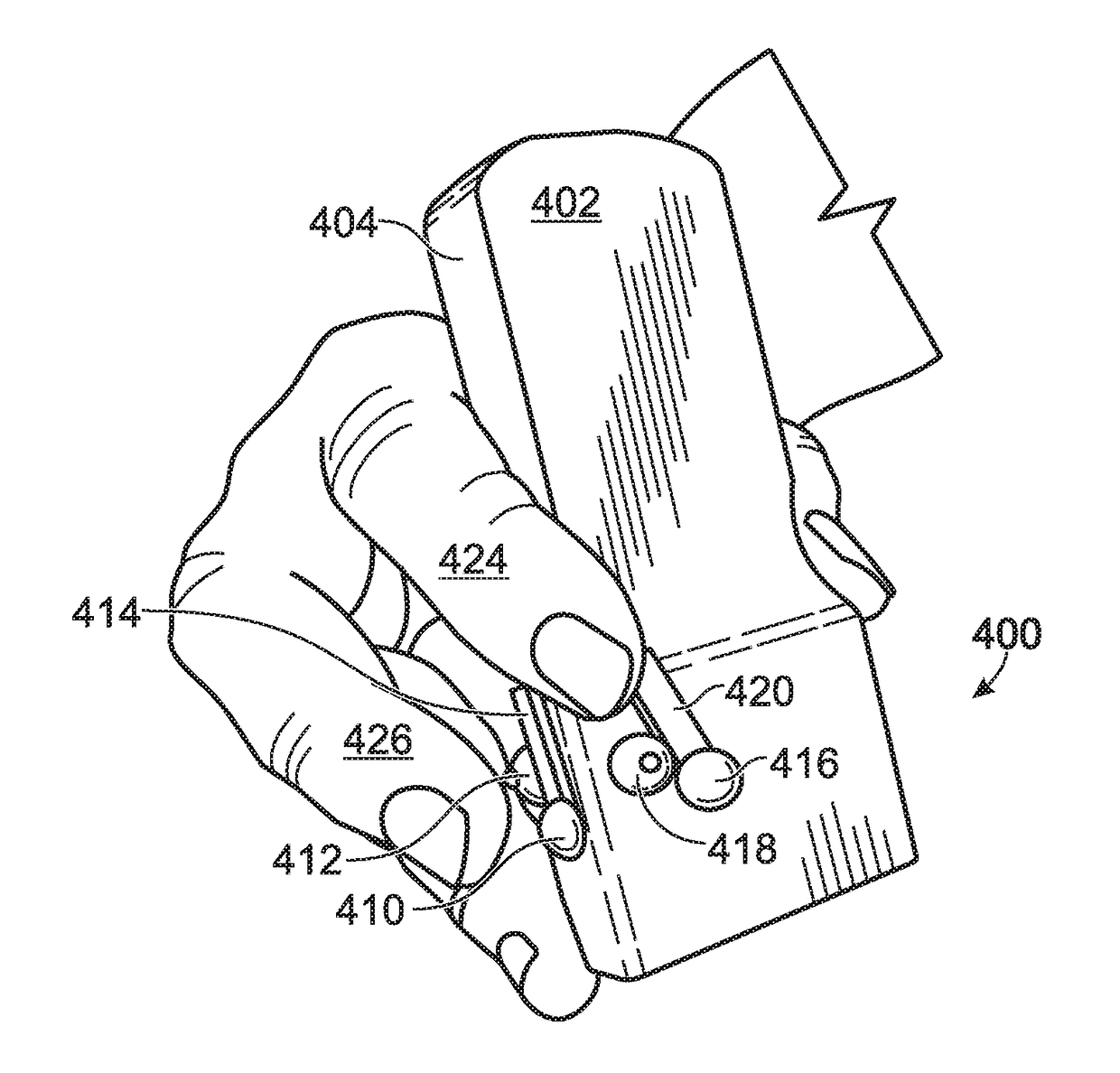
[0018]“Distal end” in this context refers to the end of an ultrasound wand located closest to the part of the body being scanned.

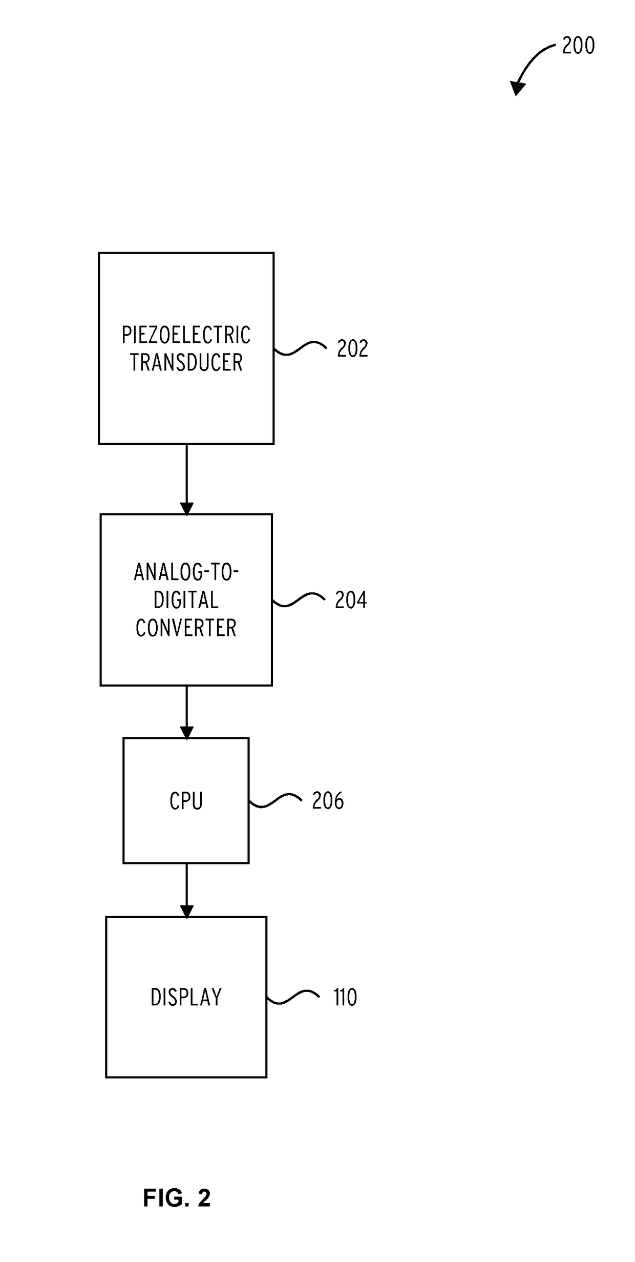
[0019]“Front end” in this context refers to a set of analog signal conditioning circuitry that uses sensitive analog amplifiers to provide a configurable and flexible electronics functional block which is used to interface a variety of sensors to an analog to digital converter.

[0020]“Front end analog-to-digital converter” in this context refers to a means for converting an analog input signal to a digital signal.

[0021]“Proximal end” in this context refers to the end of the ultrasound wand traditionally attached to computerized ultrasound equipment and furthest away from the body part being scanned.

[0022]“Slide bar” in this context refers to a manipulable button or other control element attached to the ultrasound wand by a first end which may be used to scroll through a menu on a display and select one or more items.

[0023]Described herein is an ultr...


PUM


Abstract

An ultrasound probe is provided including a probe body with a sensing face arranged to be held in contact with a patient by a user. The probe provides a plurality of groups of control elements located on two or more exterior surfaces of the probe body sufficiently close to the distal end of the probe such that a user can interact with the control elements while maintaining the scanning position of the ultrasound probe.

Description

BACKGROUND[0001]An ultrasound image is created by transmitting high frequency sound waves from a transducer in an ultrasound probe into the body and then interpreting the intensity of the reflected echoes in real time. The echos are commonly used to produce two dimensional, three-dimensional, and color flow images of internal anatomical features of patients.[0002]Current ultrasound systems often require an operator to hold an ultrasound probe in one hand while entering information onto a control panel (console) with the other, frequently non-dominant, hand. As the number of functions performed by ultrasound systems increases, the complexity of the user interface, i.e. the console, also increases. This complexity makes it inefficient and time consuming to acquire and optimize images. Additionally, in procedures where the ultrasound is being used as a guide, such as during a needle biopsy, at least three hands are generally used; one to scan, one to hold the needle, and at least one t...

Claims


Application Information

Patent Timeline
Patent Type & Authority Applications(United States)
IPC IPC(8): A61B8/00
CPCA61B8/4455A61B8/4472A61B8/54A61B8/467A61B8/465
Inventor HUNTER, VALERIE
Owner YOR LABS INC
Why Eureka
Try Eureka