Firearm noise and flash suppressor having ratcheted collet locking mechanism

a technology of collet locking mechanism and suppressor, which is applied in the field of firearms, can solve the problems of affecting the sound and flash of the flash, the noise of the collet being ratcheted, and the threaded connection becoming difficult to separate, so as to reduce the propellant gas pressure, improve the attenuation of the sound and flash, and reduce the noise

Inactive Publication Date: 2018-03-01
LARUE MARK C
View PDF0 Cites 20 Cited by
  • Summary
  • Abstract
  • Description
  • Claims
  • Application Information

AI Technical Summary

Benefits of technology

[0015]A primary flow path is defined centrally of the suppressor housing for propellant processing and discharge, the primary flow path terminating at a central discharge opening of a front wall of the suppressor housing. The suppressor mounting adapter, the internal baffles and spacer members cooperate with the internal surface of the tubular housing to define a secondary propellant gas flow path which terminates at secondary discharge openings of the front wall of the housing w...

Problems solved by technology

When suppressors employ threaded connection between the various components the threads typically become fouled to the point that the threaded connections become difficult to separate.
When the firearm is fired the suppressor housing is subjected to significant internal pressure which causes minute separation of the threaded connections and drive gunpowder residue into the threads, essentially causing locking of the threads which prevents them from being unthreaded, such as for cleaning.
When a welded suppressor device is employed, repeated firing of the firearm typically causes continuous fouling of the baffles, chambers and threads of the suppressor by accumulation of cartridge powder residue.
Thus, when the threads of the suppressor or the threads of a firearm barrel become fouled it may be difficult or impossible to remove clean and reassemble the components of a suppressor device.
This undesirable characteristic is common to most types of suppressors and represents a distinct disadvantage when servicing firearm components during field conditions.
Another disadvantage of firearm suppressor use is the problem of suppressor in...

Method used


Image

  • Firearm noise and flash suppressor having ratcheted collet locking mechanism
  • Firearm noise and flash suppressor having ratcheted collet locking mechanism
  • Firearm noise and flash suppressor having ratcheted collet locking mechanism

Examples


Embodiment Construction

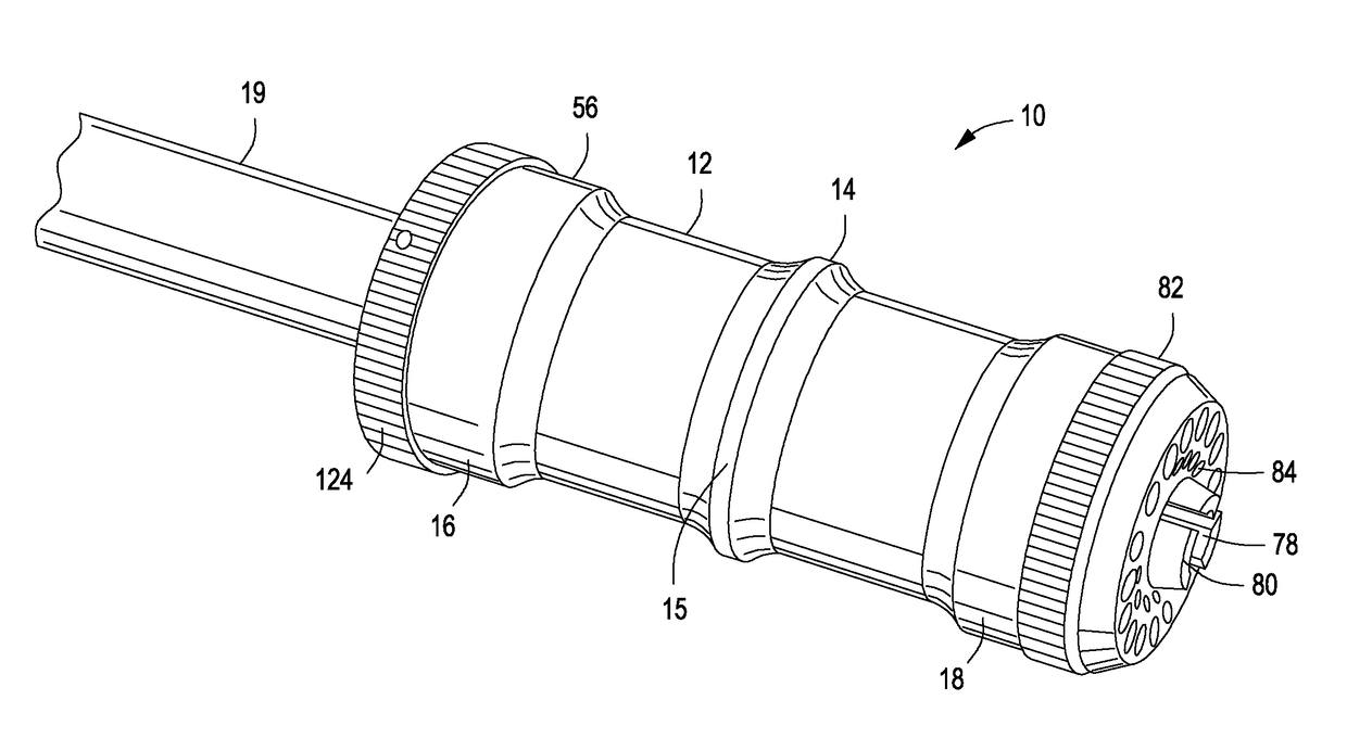
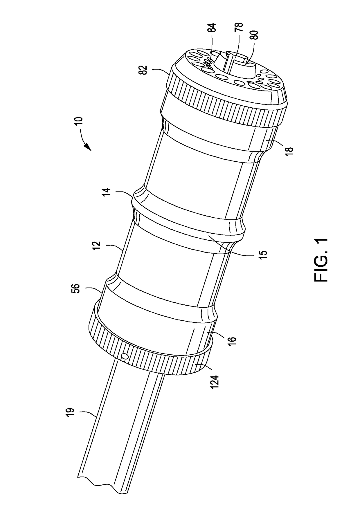
[0033]Referring now to the drawings and first to FIG. 1, a sound and flash suppressor embodying the principles of the present invention is shown generally at 10 and includes a generally cylindrical housing 12 having at least one annular intermediate structural ridge 14 to enable the housing to withstand the internal pressure that occurs when a firearm cartridge is discharged. The structural ridge and other external enlargements of the suppressor housing are knurled as shown at 15 to facilitate ease of rotational assembly as the suppressor is threaded onto a suppressor adapter of a firearm barrel. The housing is also strengthened against damage by cartridge gas pressure by structurally sound annular enlarged end sections 16 and 18 which are also externally knurled. The sound and flash suppressor 10 is shown in FIG. 1 to me mounted to the forward or muzzle end of a gun barrel 19 to which a suppressor mounting adapter 20 is secured.

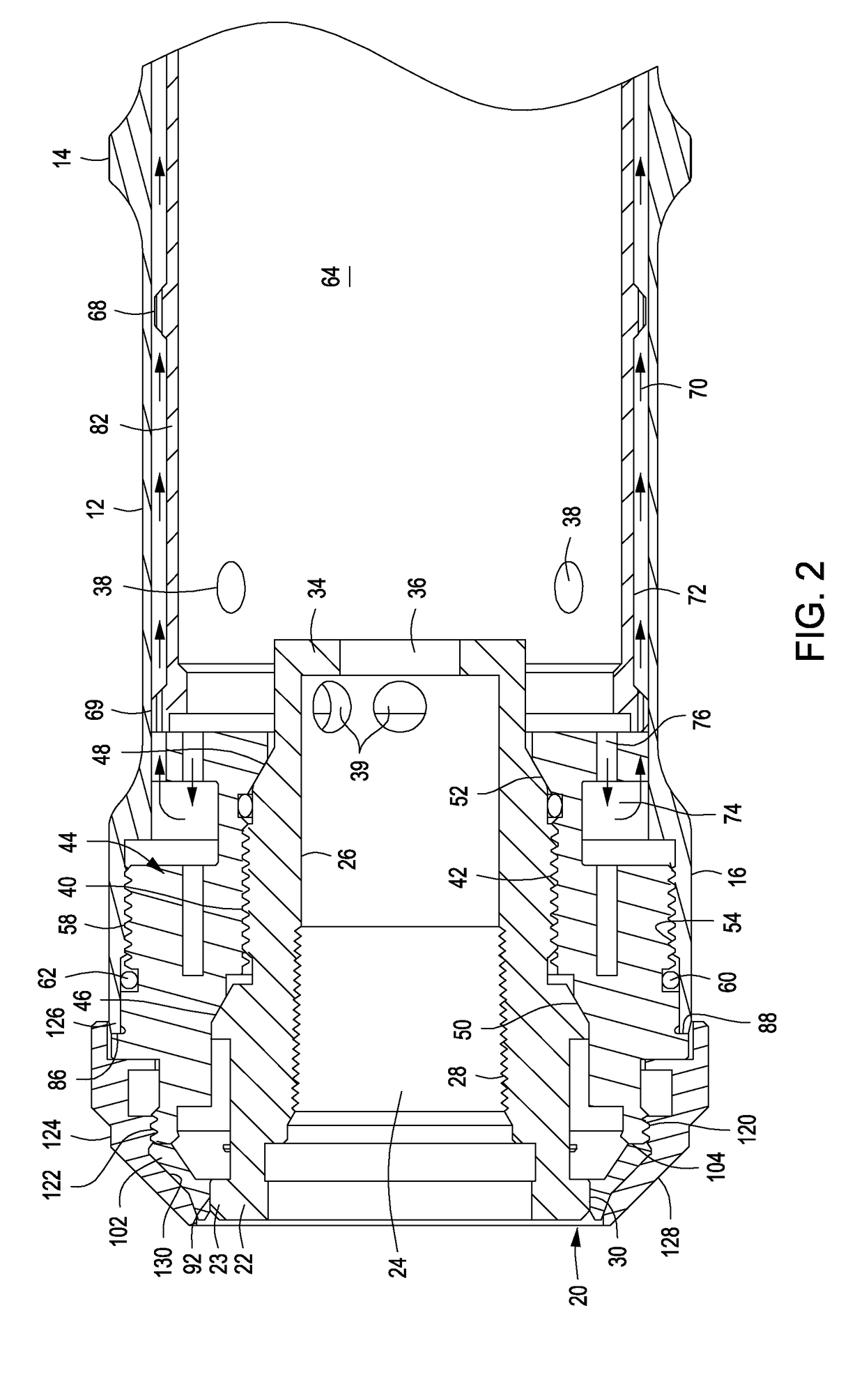
[0034]Within the suppressor housing 12 there is provid...


PUM


Abstract

A sound and flash suppressor having a tubular suppressor housing is releasably secured to a suppressor mounting adapter that is threaded to a firearm barrel. An annular locking collet is defined by a housing mounting adapter and has a plurality of spring collet fingers each having an internal ratcheted locking surface and being moveable to locking and release positions relative to an externally ratcheted locking surface of the suppressor mounting adapter A locking ring is supported by the suppressor mounting adapter and is rotatable for actuating the spring collet fingers to locking positions locking the tubular suppressor housing against loosening or separation movement relative to the suppressor mounting adapter. The locking ring is rotatable in a release direction permitting spring movement of the spring locking fingers to their release positions.

Description

BACKGROUND OF THE INVENTIONField of the Invention[0001]The present invention relates generally to firearms, particularly tactical rifles and more specifically concerns devices for suppressing the loud and sharp noise that is typically emitted during firing activity and for suppressing the flash of burning gunpowder that occurs and can be seen by others during daylight and particularly at night or under conditions of low light. More specifically, the present invention concerns mounting mechanisms for securing suppressor devices to the threaded end of a firearm barrel and for simply and efficiently locking suppressor devices to minimize the potential for suppressor devices becoming loose and possibly falling free of a firearm barrel especially during sustained firing activity.Description of the Prior Art[0002]A significant number of firearm sound suppressor devices and flash suppressor devices, generally referred to as suppressors herein, have been developed over the years for use wit...

Claims


Application Information

Patent Timeline
IPC IPC(8): F41A21/32F41A21/30F41A21/34
CPCF41A21/325F41A21/34F41A21/30
Inventor LARUE, MARK C.
Owner LARUE MARK C
Why Eureka
Try Eureka