
System, method and apparatus for making evident diesel exhaust fluid contamination

Active Publication Date: 2018-03-01
FORD GLOBAL TECH LLC
View PDF7 Cites 1 Cited by
  • Summary
  • Abstract
  • Description
  • Claims
  • Application Information

AI Technical Summary

Benefits of technology

The patent text discusses ways to reduce harmful emissions from diesel engines, specifically CO emissions, unburned hydrocarbons, particulate emissions, and NOx emissions. However, measures to reduce one type of emissions may make it harder to reduce others. The text also discusses the importance of NOx reduction measures and the need to determine who is responsible for contamination in the DEF system and prevent further damage by providing early notification of contamination. The technical effect of the patent is to provide a method to quickly and accurately determine if contamination is present in the DEF system and allow for timely remediation or replacement of the system.

Problems solved by technology

Measures to reduce one class of emissions may make efforts to reduce others more challenging.
However, the excess air in the lean mixture may tend to increase the amount of NOx produced.
Because of their relative proximity cross contamination is possible.
For example, if contaminated: the effectiveness of reducing NOx with the DEF may be reduced; the remaining DEF may be consumed more quickly than it would otherwise be consumed; the contaminated DEF may cause the SCR system to malfunction, and may damage the engine's exhaust management equipment; and a malfunctioning SCR system may cause the engine to shut down, or cause a vehicle equipped with the system to operate at very slow speeds.
In addition, the presence of the contamination in the DEF storage tank may void the equipment manufactures warranty.
Once the hydrocarbons are in the reductant system the system may have to be, replaced or, taken apart, cleaned, and rebuilt with some new, and typically expensive, components to replace those that may be destroyed.
These too, may be vulnerable to contamination.
The problem with the test strips is that the strip must be put into the fluid of the tank or a sample of the fluid must be brought out of the tank in order to test the fluid.
This makes such testing difficult or impossible and so the suspected system must be removed and opened in order to complete the test.
This removal and opening of the system is difficult and expensive in itself.

Method used


Image

  • System, method and apparatus for making evident diesel exhaust fluid contamination
  • System, method and apparatus for making evident diesel exhaust fluid contamination
  • System, method and apparatus for making evident diesel exhaust fluid contamination

Examples


Embodiment Construction

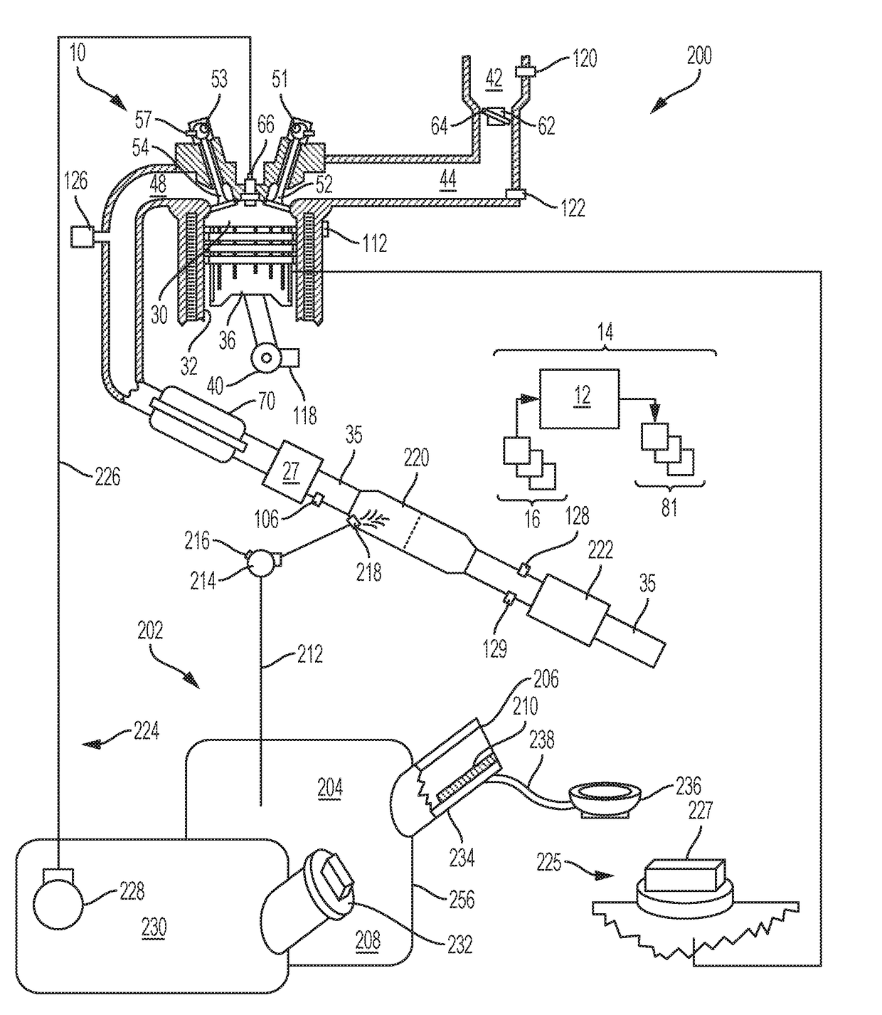
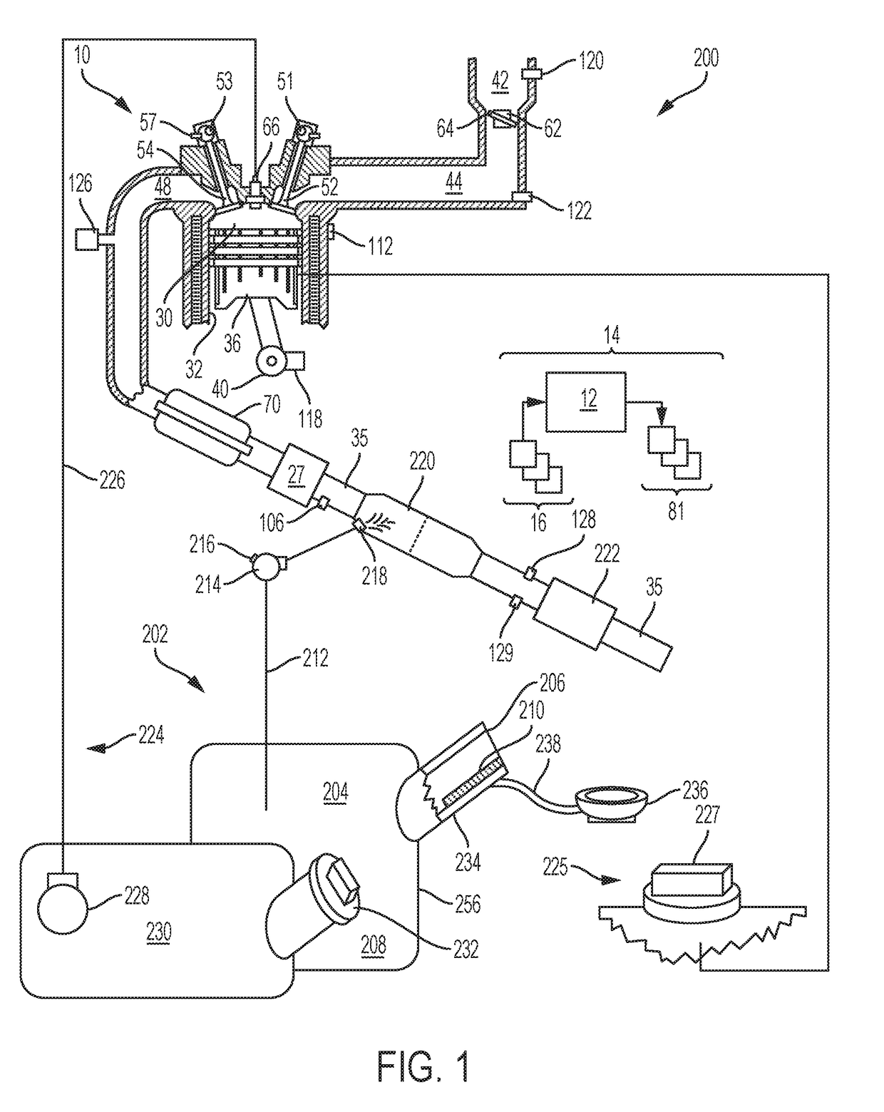
[0019]FIG. 1 is a schematic diagram showing one cylinder of multi-cylinder engine 10, which may be included in a propulsion system of an automobile. Engine 10 may be controlled at least partially by a control system including controller 12 and by input from a vehicle operator 132 via an input device 130. In this example, input device 130 includes an accelerator pedal and a pedal position sensor 134 for generating a proportional pedal position signal PP. Combustion chamber (i.e., cylinder) 30 of engine 10 may include combustion chamber walls 32 with piston 36 positioned therein. Piston 36 may be coupled to crankshaft 40 so that reciprocating motion of the piston is translated into rotational motion of the crankshaft. Crankshaft 40 may be coupled to at least one drive wheel of a vehicle via an intermediate transmission system. Further, a starter motor may be coupled to crankshaft 40 via a flywheel to enable a starting operation of engine 10. A lubrication system in the form of oil dis...


PUM


Abstract

A system, method and apparatus for making evident, diesel exhaust fuel (DEF) contamination is provided. The system, for use with a diesel exhaust fluid system, includes a container having an opening to receive a diesel exhaust fluid. A reactive device is located near the opening and reactive upon exposure to one or more predetermined components potentially present in a fluid pourable into the container through the opening. The reactive device is not reactive to the diesel exhaust fluid.

Description

FIELD[0001]The present disclosure relates to the selective catalytic system (SCR) for use with a diesel engine and, in particular, systems, methods, and mechanisms to make contamination of a diesel exhaust fuel evident.BACKGROUND AND SUMMARY[0002]Efforts to reduce harmful emissions from diesel engines may include reducing CO emissions, unburned hydrocarbons, particulate emissions, and NOx emissions. Measures to reduce one class of emissions may make efforts to reduce others more challenging. For example, running a diesel engine with a lean burn air-to-fuel ratio may increase soot combustion and reduce the level of unburned fuel in the exhaust. However, the excess air in the lean mixture may tend to increase the amount of NOx produced. Conversely, effective techniques to reduce NOx may allow for more aggressive soot combustion. This interdependence, may further increase the importance of NOx reduction measures.[0003]Measures to reduce NOx, may include selective catalytic reduction (S...

Claims


Application Information

Patent Timeline
IPC IPC(8): G01M15/10G01N21/78G01N33/28
CPCG01M15/102G01N33/2835G01N21/78G01M15/02G01N33/0004
Inventor SZYMUSIAK, SCOTT J.LAWRENCE, DONALD M.
Owner FORD GLOBAL TECH LLC
Learn More