Fire Grate for Enhanced Combustion

Inactive Publication Date: 2011-01-13
EARTHS FLAME
View PDF35 Cites 5 Cited by
  • Summary
  • Abstract
  • Description
  • Claims
  • Application Information

AI Technical Summary

Benefits of technology

[0011]In addition to supplying fresh oxygen to the secondary combustion zone of the combustion chamber, a baffle plate may be disposed over the biomass/fuel to be burned. The baffle plate interrupts the flame path rising up from the biomass/fuel being burnt in the sense of velocity, direction and turbulence. The interruption of the flame path encourages larger incompletely burned harmful particulate to fall out of the combustion gas stream and may be reentrained in the combustion gas stream at an earlier point and rise back up toward the baffle plate. This allows the harmful particulate to stay within the flame path for a longer period of time (i.e., longer residence time) and promotes more complete combustion thereby reducing harmful emissions. There are generally less harmful particulate, the more time the particulate stays within the combustion chamber. Also, a more complete combustion is promoted thereby reducing harmful emissions. The baffle plate may be fabricated from a refractory material or another material having good insulation characteristics. As such, the baffle plate increases the temperature at the secondary combustion zone as well as the primary combustion zone to promote complete burning of the harmful particulate matter. It is also contemplated that the baffle plate may have a lower surface formed with a plurality of channels or other groove shapes to interrupt the flow of gas flowing up from the fuel source to the chimney. The channels or grooves formed in the lower surface of the baffle plate may be configured to route the combustion gas stream toward the sides of the baffle plate. When the gas stream from the sides of the baffle plate and the gas stream from the front of the baffle plate recombines above the baffle plate, turbulence may occur which promotes

Problems solved by technology

Studies have shown that fireplaces produce a significant amount of emissions (e.g., particulate, carbon monoxide, volatile organic compounds, etc.) that is harmful to humans and the environment.
These harmful emissions rise up with the combustion gas and escape through the chimney to the environment.
During operation of the fireplace, the biomass/fuel being burned consum

Method used


Image

  • Fire Grate for Enhanced Combustion
  • Fire Grate for Enhanced Combustion
  • Fire Grate for Enhanced Combustion

Examples


Example

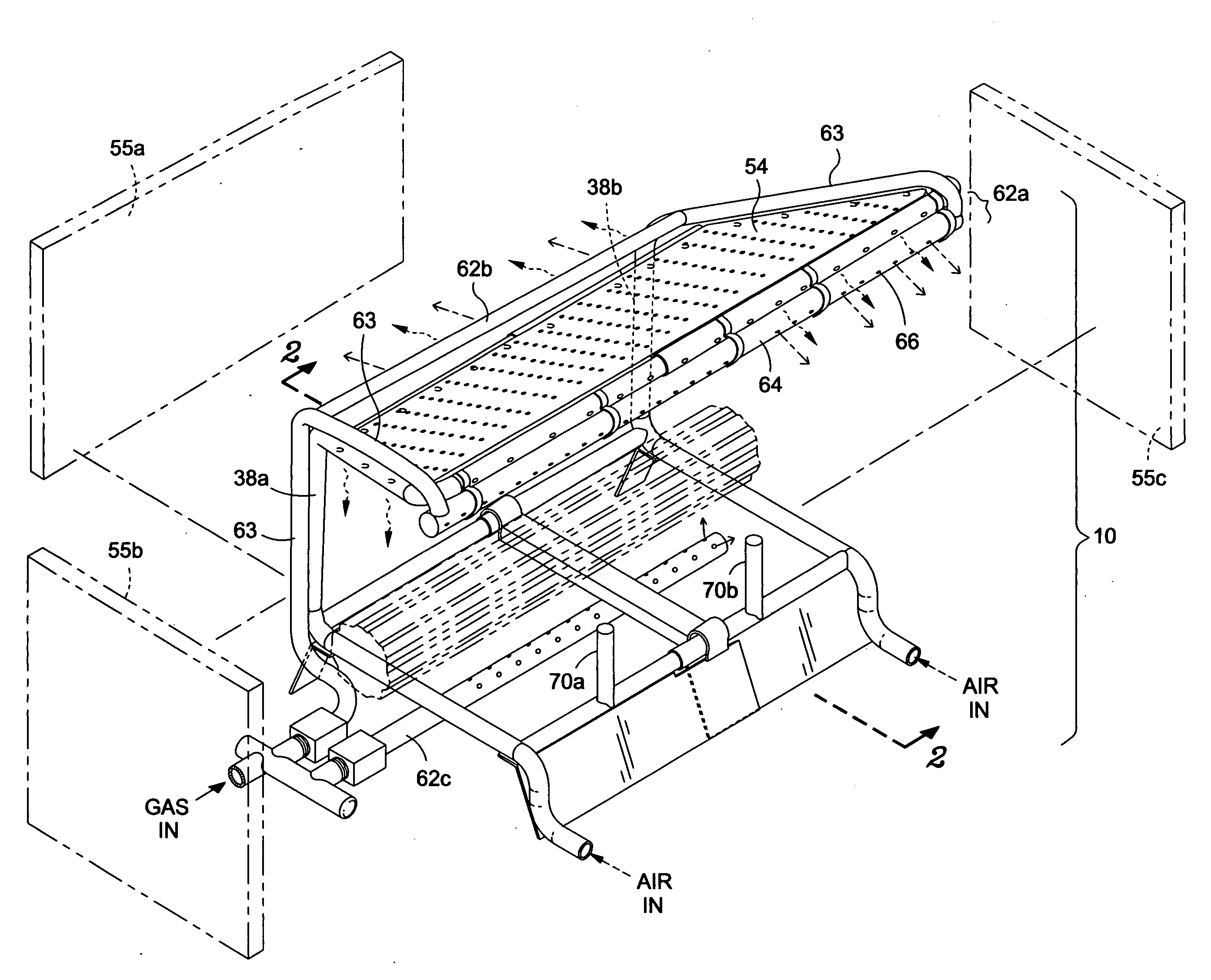
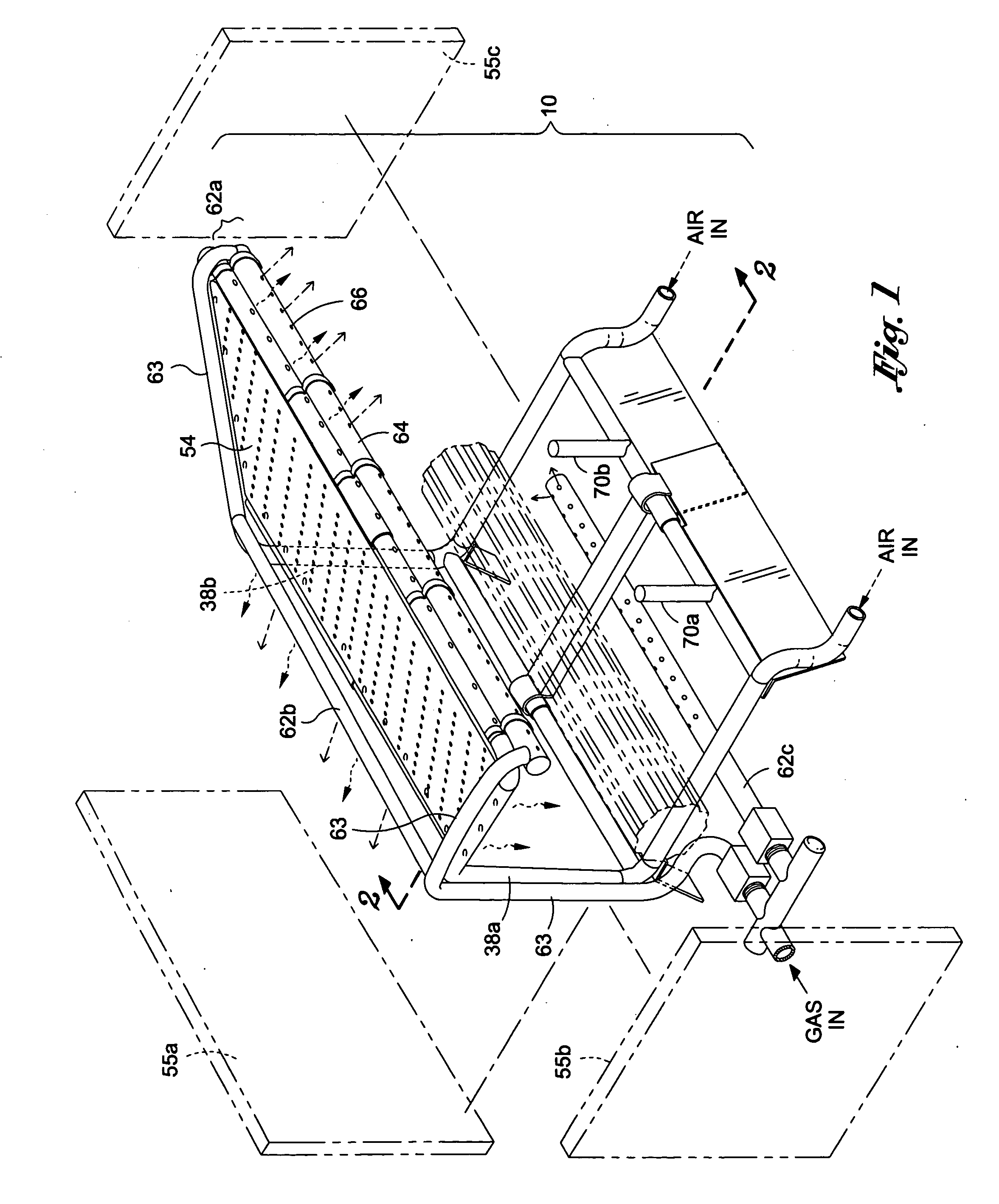
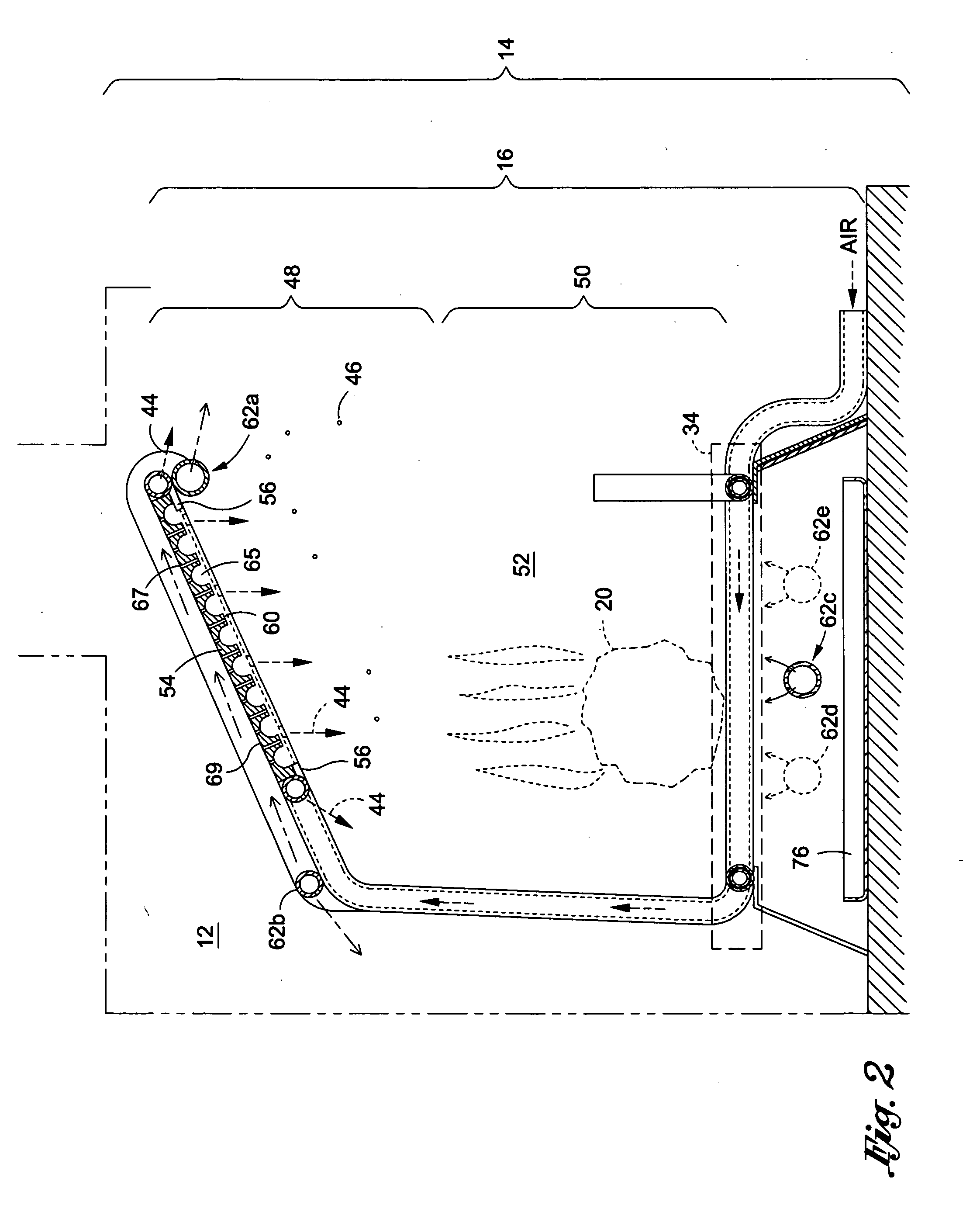
[0023]Referring now to the drawings, an improved fire grate 10 for enhanced combustion is shown. The improved fire grate 10 may be disposed within a combustion chamber 12 (see FIG. 2) of a fireplace 14. The improved fire grate 10 introduces oxygen rich air to a secondary combustion zone 50 of the combustion chamber 12, retains heat within the combustion chamber 12 to increase a temperature of the combustion chamber 12, encourages mixing of oxygen rich air with oxygen starved combustion gas stream, and increases residence time of the combustion gas stream for the purpose of reducing harmful emissions during fireplace use.

[0024]Referring now to FIG. 3, an exploded view of the improved fire grate 10 is shown. The improved fire grate 10 may be fabricated from a tubular design made from a cost effective material (e.g., steel, aluminum ceramics, etc.) of appropriate temperature and chemical resistance characteristic. The fire grate 10 may have an adjustable width 22. To this end, the impr...


PUM


Abstract

An improved fire grate may provide fresh oxygen rich air to a secondary combustion zone, created by the improved fire grate, of a combustion chamber where a combustion gas stream is typically oxygen starved assisting in the burning process of incompletely burned particulates and reducing other harmful emissions. A baffle plate may be introduced in the secondary combustion zone to increase a combustion chamber temperature, encourage mixing of oxygen starved air with oxygen rich air and increase a residence time of the combustion gas within the combustion chamber. These aspects of the baffle plate promote more efficient burning of the biomass/fuel. Additionally, log lighter(s) may be disposed in the secondary combustion zone to increase a temperature of the combustion chamber for the purposes of reducing harmful emissions.

Description

CROSS-REFERENCE TO RELATED APPLICATIONS[0001]Not ApplicableSTATEMENT RE: FEDERALLY SPONSORED RESEARCH / DEVELOPMENT[0002]Not ApplicableBACKGROUND[0003]The improved fire grate for enhanced combustion relates to an apparatus for improving efficiency of a fireplace in relation to reduction in harmful emissions and / or heating a room.[0004]A fireplace is a structure to contain a fire for heating. The fire is contained within a firebox which defines a combustion chamber. A chimney or other flue directs combustion gas to the environment. Studies have shown that fireplaces produce a significant amount of emissions (e.g., particulate, carbon monoxide, volatile organic compounds, etc.) that is harmful to humans and the environment. These harmful emissions rise up with the combustion gas and escape through the chimney to the environment.[0005]There are three time honored principles to good combustion. They relate to time, temperature and turbulence. Time is residence time or the amount of time c...

Claims


Application Information

Patent Timeline
IPC IPC(8): F24B1/18F24B1/189
CPCF24B1/1808F24B1/191F24C3/002F24B1/199F24B1/19F24B1/193F23H3/04Y02E20/34
Inventor MARPLE, STEVE
Owner EARTHS FLAME
Why Eureka
Try Eureka