
Method of Producing an Elongate Implant Containing a Structurally Encoded Pin Through Electrical Discharge Machining

a technology of elongate implants and structural encoded pins, which is applied in the direction of osteosynthesis devices, instruments, prostheses, etc., can solve the problems of insufficient, properly recorded, and readily accessible for beneficial use, and avoid unnecessary delay or even medical errors of healthcare professionals

Active Publication Date: 2018-03-08
KIESER BRIAN +2
View PDF2 Cites 12 Cited by
  • Summary
  • Abstract
  • Description
  • Claims
  • Application Information

AI Technical Summary

Benefits of technology

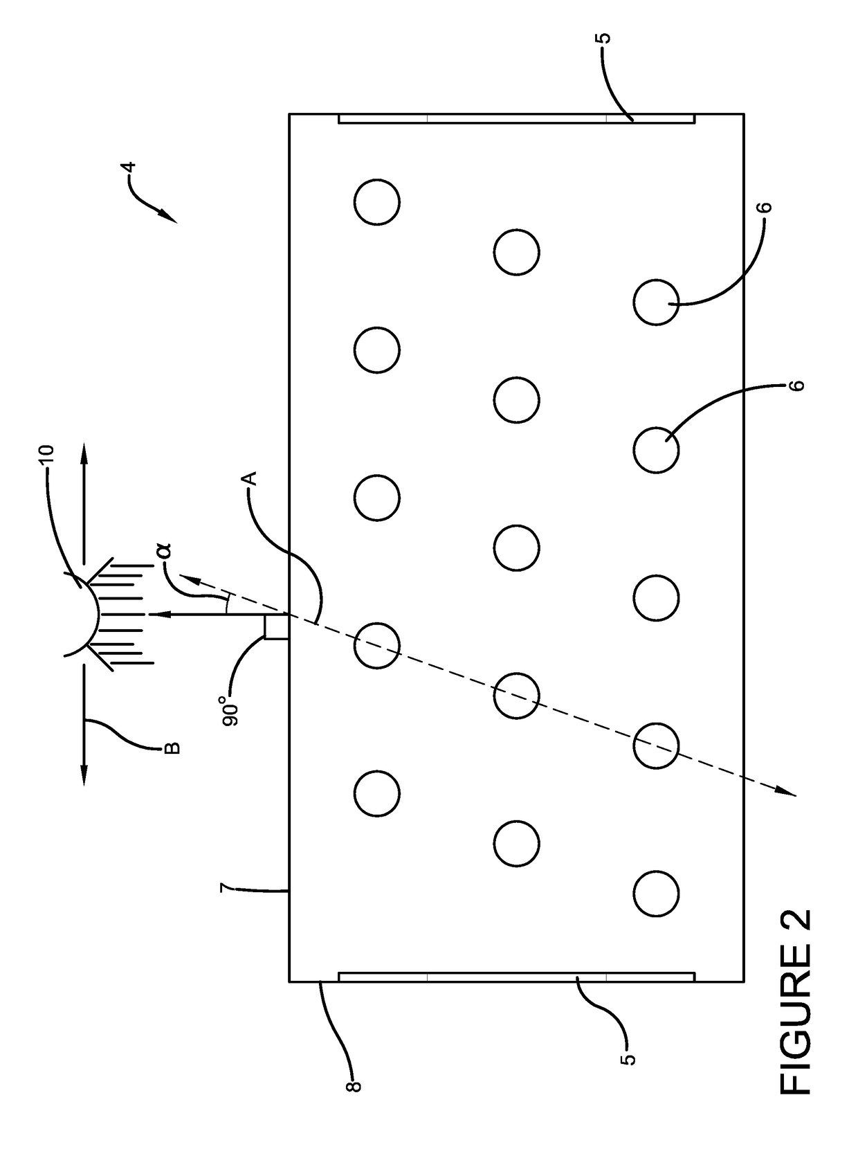
The present invention provides a method for machining notches in implants using electrical discharge machining (EDM). This method allows for the production of arrays of wires or sinkers that can be linked to software controlling the encoded patterns representing data. The method is efficient and cost-effective. The encoded data can be embedded in the elongated implant through the use of EDM, which utilizes electrical discharges to remove material from the workpiece. This technology provides a reliable and efficient way to create implants with embedded data.

Problems solved by technology

However the information, which may include without limitation the implant manufacturer and manufacturer's lot number, the date and location of surgical implantation, the responsible surgeon, any medical notes, photographs, or diagrams relating to the implant, surgery, or condition, may not be adequate, properly recorded, or readily accessible for beneficial use by a healthcare professional, implant manufacturer, or medical researcher after implantation.
Problems relating to poor implant records can lead to unnecessary delay or even medical error by healthcare professionals.

Method used


Image

  • Method of Producing an Elongate Implant Containing a Structurally Encoded Pin Through Electrical Discharge Machining
  • Method of Producing an Elongate Implant Containing a Structurally Encoded Pin Through Electrical Discharge Machining
  • Method of Producing an Elongate Implant Containing a Structurally Encoded Pin Through Electrical Discharge Machining

Examples


Embodiment Construction

[0048]In the following detailed description of the preferred embodiment, reference is made to the accompanying drawings that form a part hereof, and in which is shown by way of illustration, and not by way of limitation, a specific preferred embodiment in which the invention may be practiced. It is to be understood that other embodiments may be utilized and that changes may be made without departing from the spirit and scope of the present invention.

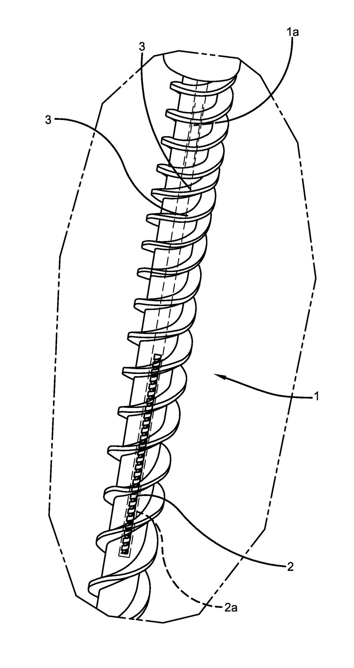
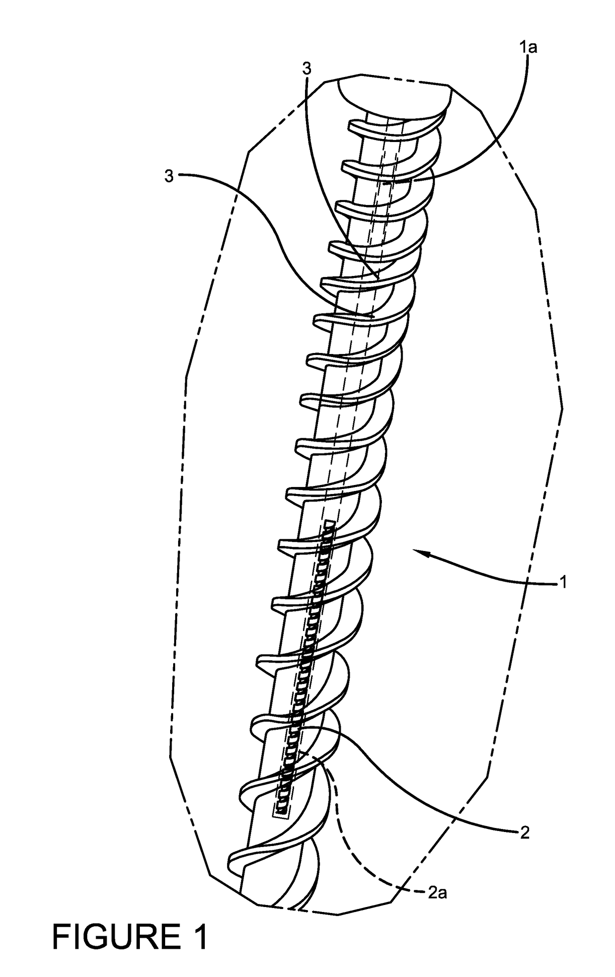
[0049]The invention generally relates to an elongate implant comprising an implant body defining a longitudinal axis; and a structurally encoded pin contained within the implant body and aligned substantially along the longitudinal axis, the structurally encoded pin comprising a shape or a plurality of surface characteristics representing structurally encoded data which may be discerned from outside the implant body via a variety of imaging modalities, a carrier for the same, and systems and methods of using both.

[0050]FIG. 1 illustrates...


PUM

PropertyMeasurementUnit
Shapeaaaaaaaaaa
Surfaceaaaaaaaaaa
Opacityaaaaaaaaaa

Abstract

An implant and method for manufacturing an implant comprising an implant body defining a longitudinal axis and a structurally encoded pin contained within the implant body and aligned substantially along the longitudinal axis, the structurally encoded pin having a shape or surface characteristics discernable by an imaging modality such as x-ray, fluoroscopy, computed tomography, electromagnetic radiation, ultrasound, visible light, UV light, magnetic resonance imaging, positron emission tomography and neutron imaging, from outside the implant body, the shape or surface characteristics representing structurally encoded data. The structurally encoded pin is encoded via an electric discharge machining process.

Description

RELATED APPLICATION DATA[0001]This application incorporates by reference all of the following in their entirety: (i) U.S. Provisional Application No. 61 / 938,475, filed Feb. 11, 2014; (ii) U.S. patent application Ser. Nos. 14 / 302,133, 14 / 302,171 (now U.S. Pat. No. 9,101,321) and 14 / 302,197, all filed Jun. 11, 2014; (iii) U.S. patent application Ser. No. 14 / 456,665, filed Aug. 11, 2014; (iv) U.S. Provisional Application No. 62 / 035,875, filed Aug. 11, 2014; (v) U.S. patent application Ser. No. 14 / 823,234, filed Aug. 11, 2015 (now U.S. Pat. No. 9,424,503); (vi) U.S. patent application Ser. No. 14 / 822,613, filed Aug. 10, 2015 (now U.S. Pat. No. 9,414,891); (vii) U.S. Provisional Application No. 62 / 204,233, filed Aug. 12, 2015; U.S. patent application Ser. No. 15 / 235,914, filed Aug. 12, 2016; (viii) U.S. Provisional Application No. 62 / 419,373, filed Nov. 8, 2016 and entitled Method of Producing Elongate Implant Containing A Structurally Encoded Pin Through Electrical Discharge Machining; ...

Claims


Application Information

Patent Timeline
IPC IPC(8): A61B90/98A61B17/86A61B17/70
CPCA61B90/98A61B17/864A61B17/8685A61B17/7002A61B17/7032A61B2017/00526A61B2090/373A61B2090/374A61B2090/3762A61B2090/378A61B2090/3925A61B2090/3937A61B2090/3954A61B2090/3966B29L2031/7532B29K2995/0056A61B6/12A61B8/0841A61B5/06A61B17/866G06K19/06A61F2250/0086A61F2250/0089G06K2019/06271B33Y80/00A61B50/20A61B50/22A61B50/30A61B50/33A61B50/34A61B2050/3008A61B2050/3011A61B90/90A61B90/96A61B17/865A61B90/39G06K7/1413A61B17/70
Inventor KIESER, BRIANZINK, THOMASCORDARO, NICHOLAS M.
Owner KIESER BRIAN
Learn More