Substrate for sensor, physical quantity detection sensor, acceleration sensor, electronic apparatus, vehicle, and method of manufacturing substrate for sensor

a technology of physical quantity detection and substrate, which is applied in the direction of acceleration measurement using interia forces, instruments, coatings, etc., can solve the problems of inability to meet the set detection range of a physical quantity such as acceleration, and the inability to accurately form the gap portion. , to achieve the effect of enhancing the accuracy of the predetermined gap wg of the gap portion

Active Publication Date: 2018-03-08
SEIKO EPSON CORP
View PDF0 Cites 7 Cited by
  • Summary
  • Abstract
  • Description
  • Claims
  • Application Information

AI Technical Summary

Benefits of technology

[0012]According to this application example, the gap portion having a predetermined gap is formed between the movable section and the support portion extending along the movable section from the base section, and the ridge portion having a top portion protruding as an etching residue is formed on each of the facing surfaces of the movable section and the support portion in the gap portion. The inventors of the invention have found that the shape of each of the ridge portions facing each other can be formed to be controlled to a desired shape by making an opening width of an etching mask a predetermined width when forming the gap portion having such a configuration by wet etching. In this regard, it becomes possible to accurately form the gap of the gap portion.
[0054]In this application example, the shape of the first recessed portion which is formed by wet-etching the second surface by using the mask pattern having the width Wp of the first pattern opening which is calculated by Expression (8) as an etching resist is formed as a recessed portion having the second inner wall surface combination in the above application example, and the opening width of an opening portion (the second opening portion) is wider than the opening width of an opening portion (the first opening portion) of the second recessed portion having the first inner wall surface combination which is formed by wet-etching the first surface by using the mask pattern having the width Wp of the second pattern opening which is calculated by Expression (9) as an etching resist. Therefore, according to the combination of the pattern openings of this application example, by first forming a recessed portion by the second inner wall surface combination having a larger opening portion from the second surface side, then forming a recessed portion by the first inner wall surface combination having a smaller opening portion from the first surface side, and penetrating the recess bottom portions of the respective recessed portions, it is possible to form the first ridge portion and the second ridge portion in a state where the accuracy of the predetermined gap Wg of the gap portion is enhanced, and it becomes possible to accurately form the gap portion in a shorter time than in the formation of the gap portion by the third inner wall surface combination and the first inner wall surface combination of the above application example.

Problems solved by technology

In the physical quantity detection sensor having such a configuration, in a case where impact exceeding a design value is applied thereto, or the like, if the displacement of the movable section is increased beyond the design value, the movable section comes into contact with an undesirable place, or excessive stress is applied to a connection portion between the movable section and the base section, whereby there is a concern that the substrate for a sensor or the physical quantity detection element may be broken.
Incidentally, in the quartz crystal which is suitably used as a material for forming the substrate for a sensor of the physical quantity detection sensor, it is known that a crystal has a diamond structure and when forming the outer shape of the substrate for a sensor by wet etching, because of an etching anisotropy due to a difference in etching rate in the respective crystal axis directions of the quartz crystal, it is difficult to accurately form a gap in the in-plane direction between the movable section and the support portion at a desired length.
Further, in a case where the gap between the movable section and the protrusion portion (the restricting portion) becomes shorter than an appropriate length, the displacement range of the movable section is restricted to be smaller than in the setting, and therefore, there is a concern that the set detection range of a physical quantity such as acceleration may not be able to be satisfied.

Method used


Image

  • Substrate for sensor, physical quantity detection sensor, acceleration sensor, electronic apparatus, vehicle, and method of manufacturing substrate for sensor
  • Substrate for sensor, physical quantity detection sensor, acceleration sensor, electronic apparatus, vehicle, and method of manufacturing substrate for sensor
  • Substrate for sensor, physical quantity detection sensor, acceleration sensor, electronic apparatus, vehicle, and method of manufacturing substrate for sensor

Examples


embodiment 1

Physical Quantity Detection Sensor

[0082]Hereinafter, a physical quantity detection sensor according to Embodiment 1 will be described using FIGS. 1 and 3.

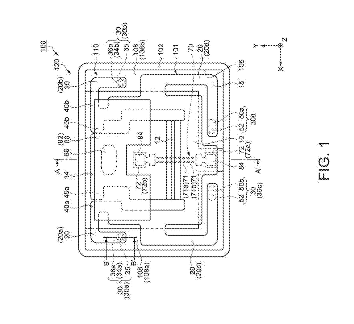
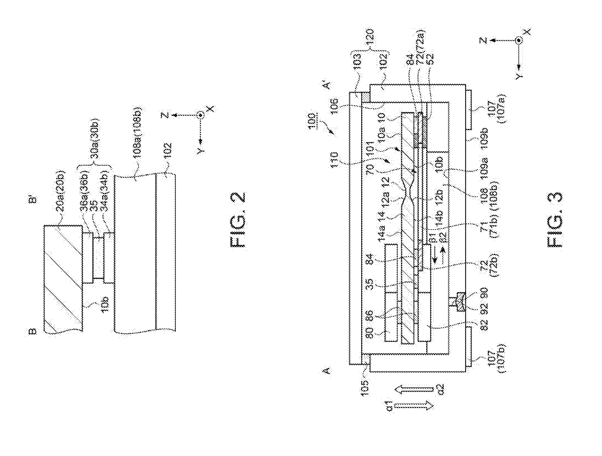
[0083]FIG. 1 is a plan view showing the configuration of a physical quantity detection sensor 100 according to this embodiment. FIG. 3 is a cross-sectional view showing the configuration of the physical quantity detection sensor 100 and is a cross-sectional view of a portion indicated by line segment A-A′ in FIG. 1. In FIGS. 1 and 3, as three axes orthogonal to each other, an X-axis, a Y-axis, and a Z-axis are shown. The Z-axis is an axis indicating a direction in which the gravity acts.

[0084]Further, for convenience of description, illustration of a lid 103 is omitted in FIG. 1.

[0085]In this embodiment, description will be made with seeing the physical quantity detection sensor 100 from a Z-axis direction regarded as being viewed in a planar view.

[0086]The physical quantity detection sensor 100 has a physical quantity detection de...

embodiment 2

[0223]Hereinafter, modification examples of the cantilever section 101 as the substrate for a sensor in the physical quantity detection sensor 100 of the embodiment described above will be described with reference to the drawings. The same configurations as those in the embodiment described above are denoted by the same reference numerals and overlapping description is omitted.

[0224]FIG. 8 is a partial cross-sectional view showing a cantilever section 101B as a substrate for a sensor according to Embodiment 2 with the same cross section as that in FIG. 6.

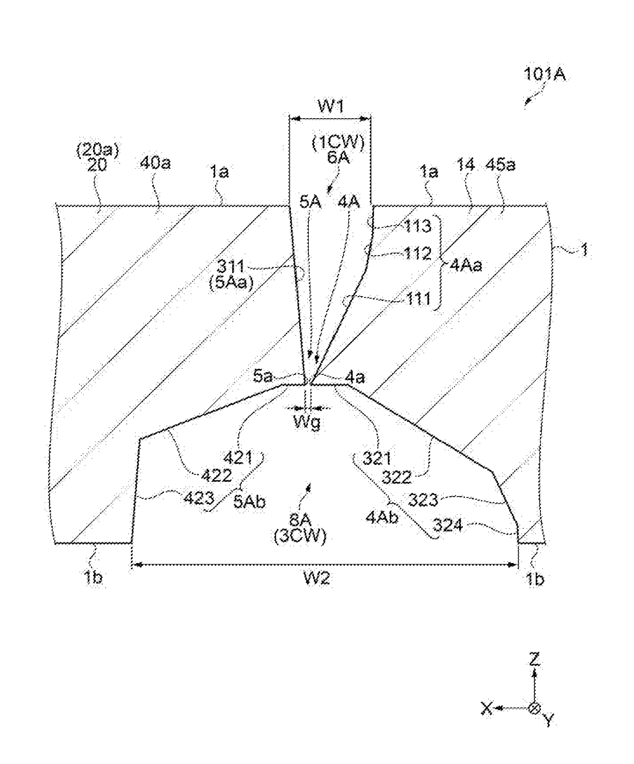
[0225]In FIG. 8, a gap portion of the cantilever section 101B according to Embodiment 2 is formed by causing a second opening portion 8B, which is formed on the second surface 1b side of the quartz crystal substrate 1 and is the same third inner wall surface combination 3CW as that of the second opening portion 8A (refer to FIG. 6) in the cantilever section 101A of Embodiment 1, and a first opening portion 6B of the second inner wal...

embodiment 3

[0235]FIG. 9 is a partial cross-sectional view showing a cantilever section 101C according to Embodiment 3 with the same cross section as that in FIG. 6. In the following description of this embodiment, the same configurations as those in the embodiments described above are denoted by the same reference numerals and overlapping description is omitted.

[0236]In FIG. 9, a gap portion of the cantilever section 101C according to Embodiment 3 is formed by causing a second opening portion 8C which is formed on the second surface 1b side of the quartz crystal substrate 1 and is the second inner wall surface combination 2CW formed on the first surface 1a side in the cantilever section 101B of Embodiment 2 and a first opening portion 6C which is formed on the first surface 1a side and is the same first inner wall surface combination 1CW as that of the first opening portion 6A in the cantilever section 101A of Embodiment 1 to be penetrated to each other at substantially the center in the thick...


PUM

PropertyMeasurementUnit
thicknessaaaaaaaaaa
opening widthaaaaaaaaaa
physicalaaaaaaaaaa

Abstract

A cantilever section as a substrate for a sensor includes: a base section; a movable section connected to the base section; an arm portion as a support portion extending along the movable section from the base section when viewed in a planar view as viewed from a thickness direction of the movable section; and a gap portion formed to have a predetermined gap between the movable section and the arm portion when viewed in the planar view, in which a ridge portion formed as an etching residue having a top portion on the side facing the gap portion is provided on each of facing surfaces of the movable section and the arm portion in the gap portion, and the predetermined gap is a gap between a top portion of a first ridge portion which is the ridge portion formed at one of the movable section and the arm portion, and a top portion of a second ridge portion which is the ridge portion formed at the other of the movable section and the arm portion.

Description

[0001]This application claims the benefit of Japanese Application No. JP-2016-174308 filed Sep. 7, 2016. The disclosure of the prior application is hereby incorporated by reference herein in its entirety.BACKGROUND1. Technical Field[0002]The present invention relates to a substrate for a sensor, a physical quantity detection sensor, an acceleration sensor, an electronic apparatus, a vehicle, and a method of manufacturing a substrate for a sensor.2. Related Art[0003]In the related art, for example, as described in JP-A-2012-189480, a physical quantity detection sensor is known in which a physical quantity detection element for detecting a physical quantity is fixed to a substrate for a sensor (a cantilever section) having a base section (a fixing section), a movable section connected to the base section, and a support portion extending along the movable section from the base section when viewed in a planar view as viewed from a thickness direction of the movable section. In the physi...

Claims


Application Information

Patent Timeline
Patent Type & Authority Applications(United States)
IPC IPC(8): B81B3/00B81C1/00G01P15/10G01P15/08G01P15/12G01C19/5726
CPCB81B3/0021B81C1/0015G01P15/10G01P15/0802G01P15/123G01C19/5726B81B2203/0118B81B3/0051G01P15/0922G01P15/097B81B2201/0235
Inventor OTO, MASAYUKI
Owner SEIKO EPSON CORP
Why Eureka
Try Eureka