Method for Contamination Monitoring

a technology for monitoring and contamination, applied in the field of method for monitoring contamination, can solve the problems of difficult to avoid contamination, fluid that is generally unacceptable for hydrocarbon fluid sampling and/or evaluation, and difficulty in detecting contamination, etc., and achieve the effect of detecting stabilization of property and stabilizing property

Active Publication Date: 2018-03-08
SCHLUMBERGER TECH CORP
View PDF7 Cites 0 Cited by
  • Summary
  • Abstract
  • Description
  • Claims
  • Application Information

AI Technical Summary

Benefits of technology

The patent text describes a method for evaluating fluids from underground wellbores. The method involves drawing fluid from the formation into a flowline and measuring various physical and chemical properties of the fluid. By detecting any stabilization or changes in these properties, the method can help to identify and differentiate between different fluids in the formation. This can be useful in various oil drilling applications and improve the efficiency of wellbore construction.

Problems solved by technology

Various challenges may arise in the process of obtaining virgin fluid from subsurface formations.
This material often contaminates the virgin fluid as it passes through the borehole, resulting in fluid that is generally unacceptable for hydrocarbon fluid sampling and / or evaluation.
Such fluid is referred to herein as “contaminated fluid.” Because fluid is sampled through the borehole, mudcake, cement and / or other layers, it is difficult to avoid contamination of the fluid sample as it flows from the formation and into a downhole tool during sampling.
A challenge thus lies in monitoring the contamination of the virgin fluid during fluid extraction from the formation.

Method used


Image

  • Method for Contamination Monitoring
  • Method for Contamination Monitoring
  • Method for Contamination Monitoring

Examples


Embodiment Construction

[0017]Presently preferred embodiments of the invention are shown in the above-identified figures and described in detail below. In describing the preferred embodiments, like or identical reference numerals are used to identify common or similar elements. The figures are not necessarily to scale and certain features and certain views of the figures may be shown exaggerated in scale or in schematic in the interest of clarity and conciseness.

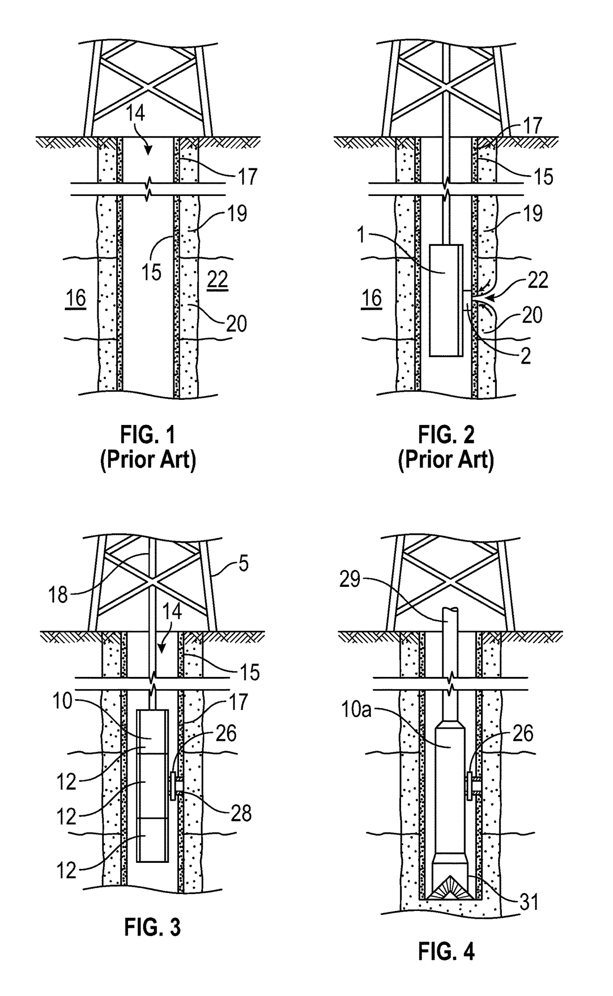
[0018]FIG. 1 depicts a subsurface formation 16 penetrated by a wellbore 14. A layer of mud cake 15 lines a sidewall 17 of the wellbore 14. Due to invasion of mud filtrate into the formation during drilling, the wellbore is surrounded by a cylindrical layer known as the invaded zone 19 containing contaminated fluid 20 that may or may not be mixed with virgin fluid. Beyond the sidewall of the wellbore and surrounding contaminated fluid, reservoir fluid or virgin fluid 22 is located in the formation 16. As shown in FIG. 1, contaminates tend to be loca...


PUM

PropertyMeasurementUnit
physical propertyaaaaaaaaaa
concentrationaaaaaaaaaa
fluid propertyaaaaaaaaaa

Abstract

A method of evaluating a fluid from a subterranean formation drawn into a downhole tool positioned in a wellbore penetrating the subterranean formation is provided. This method involves drawing fluid from a formation into a flowline, measuring at least one property of the fluid in the flowline and detecting stabilization of the property or properties of the fluid in the flowline. An electrochemical sensor for measuring contents of a fluid or gas at high pressure and / or high temperature may be used.

Description

CROSS-REFERENCE TO RELATED APPLICATIONS[0001]This application claims priority and benefit to copending Provisional U.S. Patent Application, Ser. No. 62 / 383,040, entitled: “Method for Contamination Monitoring” and filed on Sep. 2, 2016, the entirety of which is incorporated herein.BACKGROUND OF THE INVENTION[0002]Wellbores are drilled to locate and produce hydrocarbons. A downhole drilling tool with a bit at and end thereof is advanced into the ground to form a wellbore. As the drilling tool is advanced, a drilling mud is pumped through the drilling tool and out the drill bit to cool the drilling tool and carry away cuttings. The fluid exits the drill bit and flows back up to the surface for recirculation through the tool. The drilling mud is also used to form a mudcake to line the wellbore.[0003]During the drilling operation, it is desirable to perform various evaluations of the formations penetrated by the wellbore. In some cases, the drilling tool may be provided with devices to t...

Claims


Application Information

Patent Timeline
Patent Type & Authority Applications(United States)
IPC IPC(8): E21B49/08E21B43/16C09K8/58
CPCE21B49/087E21B43/16C09K8/58E21B47/00E21B49/10E21B49/0875E21B49/088
Inventor FERGUSON, RICHARDOSMAN, MAGDY SAMIR
Owner SCHLUMBERGER TECH CORP
Why Eureka
Try Eureka