Photonic switches, photonic switching fabrics and methods for data centers

a technology of photonic switches and fabrics, applied in hybrid switching systems, frequency-division multiplexing selection, instruments, etc., can solve the problems of increasing the pressure on the content upload/download speed and latency of the content, and being easy to understand

Active Publication Date: 2018-03-08
AEPONYX
View PDF8 Cites 17 Cited by
  • Summary
  • Abstract
  • Description
  • Claims
  • Application Information

AI Technical Summary

Benefits of technology

[0010]It is an object of the present invention to mitigate limitations in the prior art relating to optical networks

Problems solved by technology

With almost two billion users accessing all these websites, including a growing amount of high bandwidth video, it's easy to understand but hard to comprehend how much data is being uploaded and downloaded every second on the Internet.
At the same time consumers' expectations of download/upload speeds and latency in a

Method used


Image

  • Photonic switches, photonic switching fabrics and methods for data centers
  • Photonic switches, photonic switching fabrics and methods for data centers
  • Photonic switches, photonic switching fabrics and methods for data centers

Examples


Embodiment Construction

[0101]The present invention is directed to optical networks and more particularly to use optical switching in data center and cloud computing networks.

[0102]The ensuing description provides exemplary embodiment(s) only, and is not intended to limit the scope, applicability or configuration of the disclosure. Rather, the ensuing description of the exemplary embodiment(s) will provide those skilled in the art with an enabling description for implementing an exemplary embodiment. It being understood that various changes may be made in the function and arrangement of elements without departing from the spirit and scope as set forth in the appended claims.

[0103]1. Current State of the Art Without Optical Switching in Intra-Data Center Communications

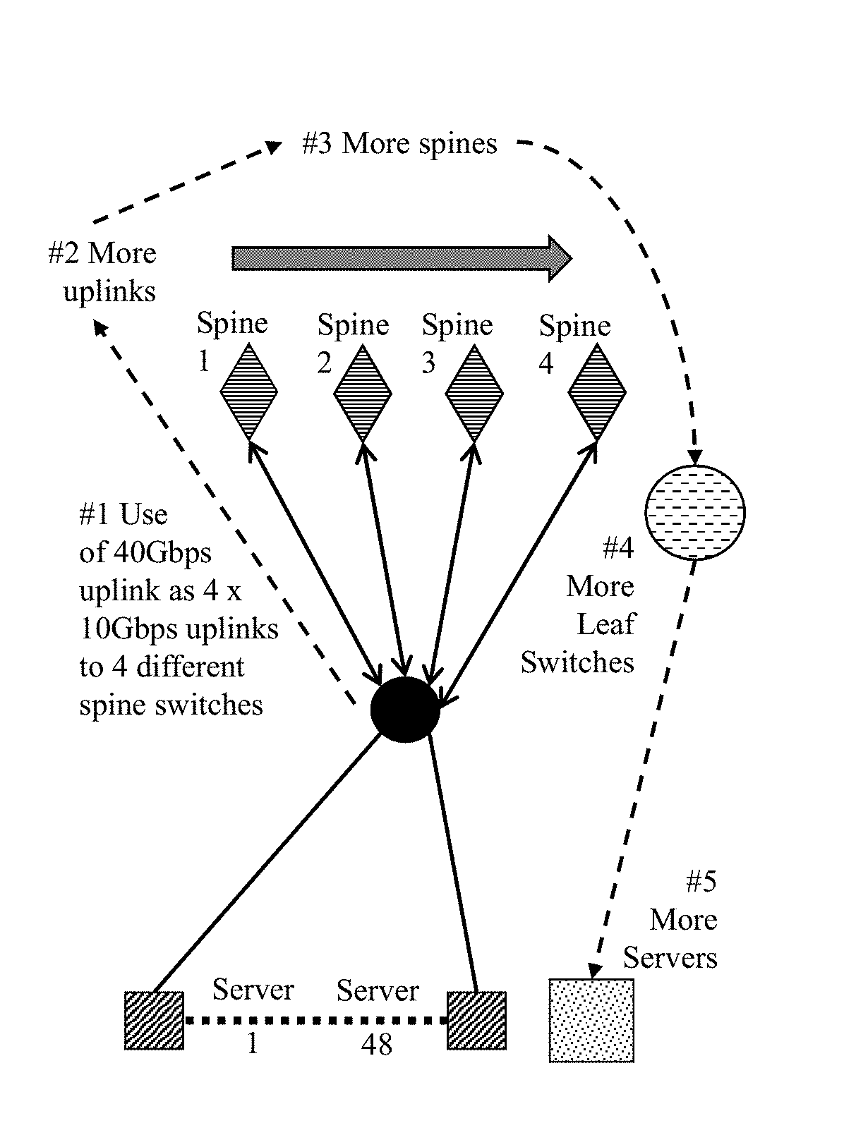
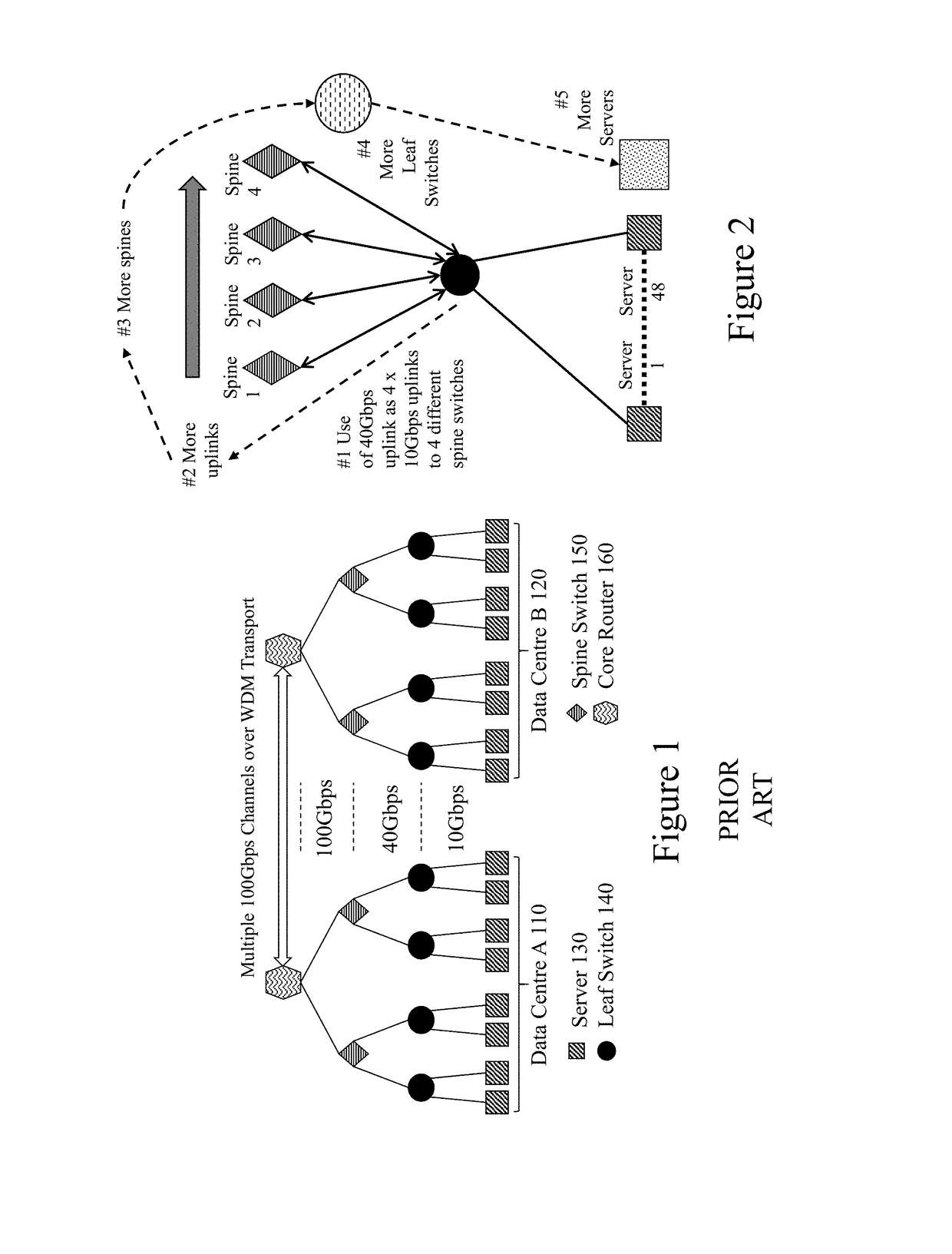
[0104]The majority of warehouse scale datacenters networks today are designed around a two-tier leaf / spine Ethernet aggregation topology leveraging very high-density switches. Servers first connect to leaf switches and then leaf switches conne...


PUM


Abstract

Data center interconnections, which encompass WSCs as well as traditional data centers, have become both a bottleneck and a cost/power issue for cloud computing providers, cloud service providers and the users of the cloud generally. Fiber optic technologies already play critical roles in data center operations and will increasingly in the future. The goal is to move data as fast as possible with the lowest latency with the lowest cost and the smallest space consumption on the server blade and throughout the network. Accordingly, it would be beneficial for new fiber optic interconnection architectures to address the traditional hierarchal time-division multiplexed (TDM) routing and interconnection and provide reduced latency, increased flexibility, lower cost, lower power consumption, and provide interconnections exploiting scalable optical modular optically switched interconnection network as well as temporospatial switching fabrics allowing switching speeds below the slowest switching element within the switching fabric.

Description

CROSS-REFERENCE TO RELATED APPLICATIONS[0001]This patent application claims the benefit of priority as a 371 National Phase Patent Application of PCT / CA2016 / 000084 filed Mar. 23, 2016 entitled “Photonic Switches, Photonic Switching Fabrics and Methods for Data Centers”, which itself claims priority from U.S. Provisional Patent Application No. 62 / 136,673 filed Mar. 23, 2015 entitled “Photonic Switches, Photonic Switching Fabrics and Methods for Data Centers”, the entire contents of each being included herein by reference.FIELD OF THE INVENTION[0002]This invention relates to photonic switches and photonic switch fabrics and more particularly to MOEMS photonic switching fabrics and photonic switching fabrics with fast and slow spatial and wavelength reconfiguration rates in combination for data center and cloud computing applications.BACKGROUND OF THE INVENTION[0003]Cloud computing is, strictly, a phrase used to describe a variety of computing concepts that involve a large number of co...

Claims


Application Information

Patent Timeline
IPC IPC(8): H04Q11/00H04J14/02
CPCH04Q11/0005H04Q11/0062H04J14/02H04Q2011/0058H04Q2011/0039H04Q2011/0073H04Q2011/0016H04Q11/02H04L12/6418G02B6/3518H04Q2011/003G02B2006/12145
Inventor MENARD, FRANCOISBERARD, MARTINBRIERE, JONATHAN
Owner AEPONYX
Why Eureka
Try Eureka