Spinal surgical instrument, method of guiding thereof and system for bone stabilization

a surgical instrument and spine technology, applied in the field of spine surgical instruments, can solve the problems of pain, numbness, weakness, incontinence, etc., and achieve the effects of reducing the influence of adverse effects, improving the success rate of surgery, and efficient and effective approach to precedent devices

Active Publication Date: 2018-03-15
WILTROM
View PDF21 Cites 8 Cited by
  • Summary
  • Abstract
  • Description
  • Claims
  • Application Information

AI Technical Summary

Benefits of technology

[0028]As described above, the spinal surgical instrument and the method of guiding thereof according to the present invention are used in conjunction with a precedent device having a guiding unit. The spinal surgical instrument includes an operating element, an extending element, a handling element and a guide element. The two ends of the extending element connect to the operating element and the handling element, respectively. In addition, the guide element is disposed on the extending element, and the guide element has a guide hole. By aligning the guide hole with the guiding unit and then making the guiding unit pass through the guide hole, the surgeon can move the spinal surgical instrument along the guiding unit in a predetermined direction to efficiently and effectively approach the precedent device for subsequent moves. Therefore, the design of the present invention addresses the problems of a limited operative space and narrow operative field encountered by surgeons during surgery. In addition, the use of the present invention can reduce the influence of the adverse effects of retraction or detachment of tissue, improve the success rate of surgery, reduce the operation time and shorten the period of postoperative recovery.
[0029]In addition, the spinal surgical instrument of the present invention can be any instrument used for placing a pedicle screw fixation system or cortical bone trajectory (CBT) screw technique. Thus, even if surgeons have to change instruments during the procedure, each of the instruments can be guided to move along a predetermined path following the guiding unit by the guiding unit passing through the guide hole. In this way, the surgeon can ensure that the spinal surgical instruments move toward or away from the screw following the original path to reduce the expansion of an incision.
[0030]Especially for minimally invasive surgery, the guiding unit of a precedent device can protrude from the surgical incision on the back of a patient, so the surgeon can clearly recognize the location of the implanted or precedent device. It is also useful for surgeons to identify or align the approach direction of surgical instruments with the guiding unit during the subsequent moves.

Problems solved by technology

Spinal disorders, especially in the lumbar region, often have a considerable impact on patients, causing pain, numbness, weakness, incontinence, dysuria, dyschezia, or other symptoms.
When symptoms are severe, the discomfort of patients usually cannot be relieved by correction, and spinal surgery is required to reposition the vertebrae.
The most difficult aspect of such surgery is locating implanted devices such as pedicle screws before approaching them with different surgical instruments in every move of the entire procedure.
However, because of muscle and ligament tissues around the incision, the surgeon cannot easily locate the implanted pedicle screws during surgery.
This approach is accompanied by an increase in blood loss, slower recovery due to anatomical destruction, severe postoperative pain, higher postoperative infection rate and other adverse effects.
Post-operative recovery in such cases can greatly extend the length of hospital stay and increase medical costs.
However, in such surgery, surgeons have much less operative space than in traditional surgery to manipulate surgical instruments.
In addition, since the muscles and connective tissues of patients block surgeons' operative field, the visibility of patients' internal physical structures is limited.
Thus, it is more difficult to locate the implanted screw in minimally invasive surgery than in traditional invasive surgery.
The abovementioned issues increase the difficulty of the engagement of a rod or a surgical instrument with a screw.
Increased difficulty and pressure on a surgeon manipulating the instrument may prolong the operation time, resulting in a burden on the patient.
These difficulties indirectly discourage surgeons from performing minimally invasive surgery.
Accordingly, for conventional or minimally invasive spinal surgery, a crucial issue is whether the surgeon can repeatedly locate an implanted screw or an expander (referred to herein as precedent devices) and then move instruments to the position stably.

Method used


Image

  • Spinal surgical instrument, method of guiding thereof and system for bone stabilization
  • Spinal surgical instrument, method of guiding thereof and system for bone stabilization
  • Spinal surgical instrument, method of guiding thereof and system for bone stabilization

Examples


first embodiment

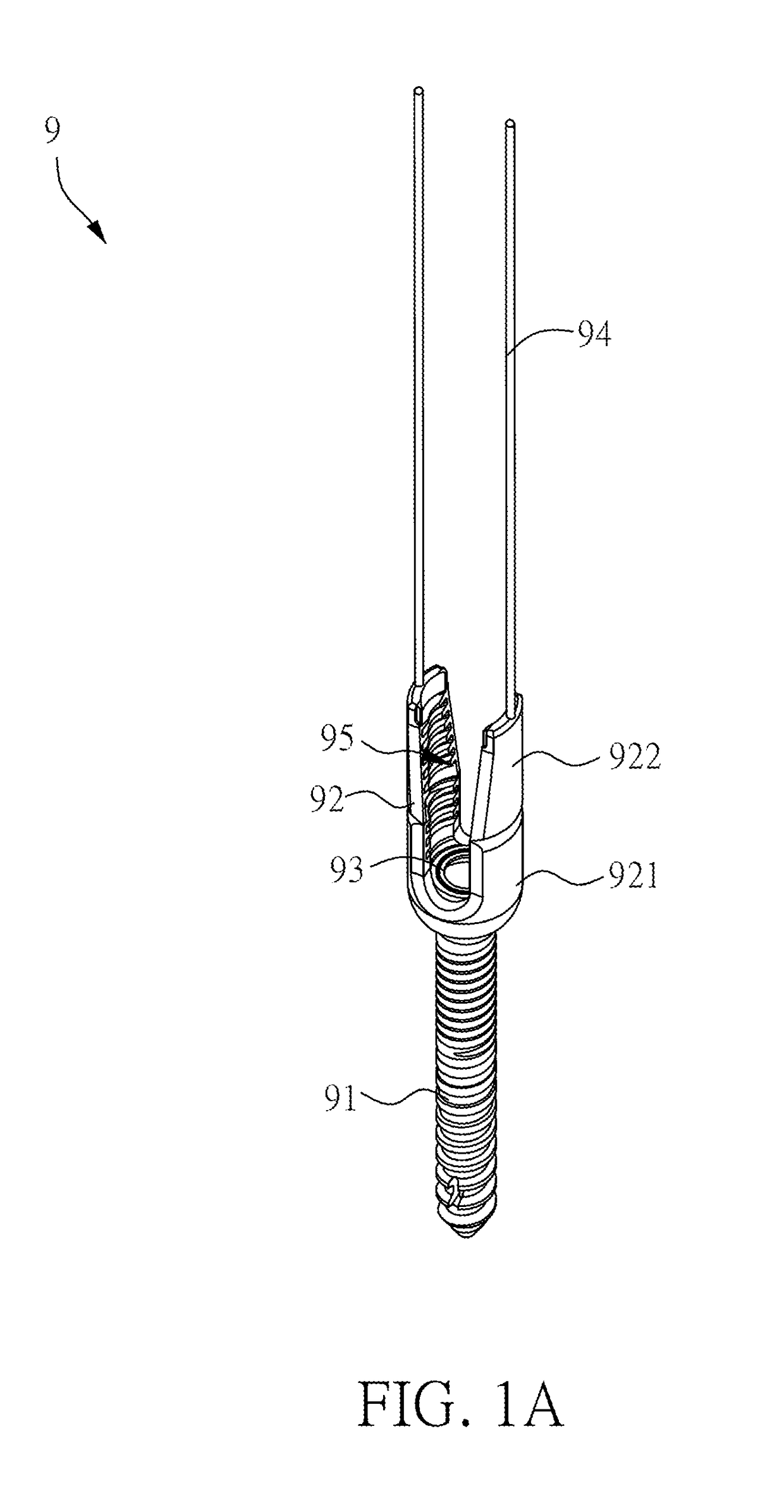
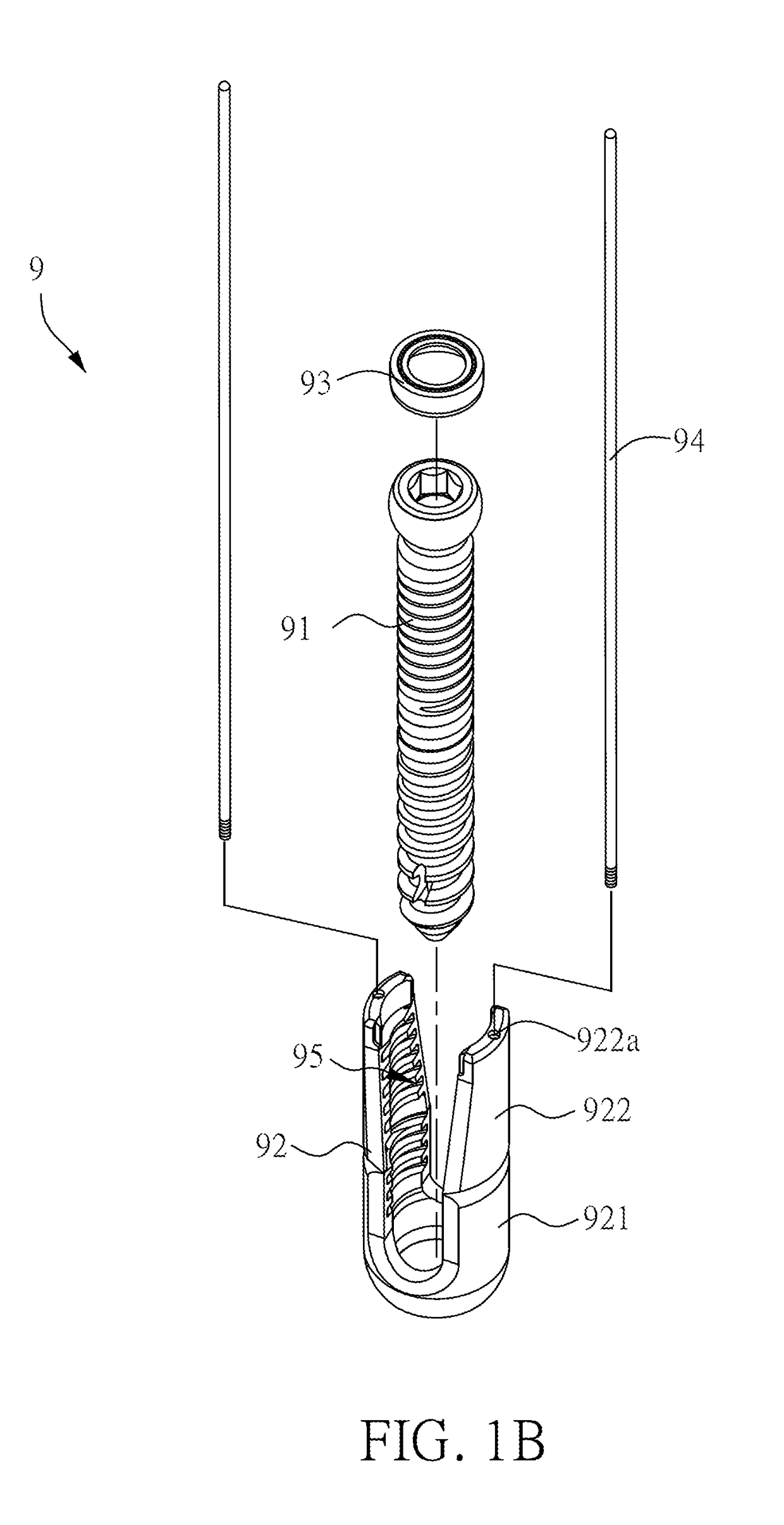
[0060]FIG. 2 is a schematic diagram of a spinal surgical instrument according to the present invention. As shown in FIG. 2, in the present embodiment, the spinal surgical instrument 1 is a pedicle screw adjuster. The spinal surgical instrument 1 includes an operating element 11, an extending element 12, a handling element 13, and a guide element 14. One end of the extending element 12 connects to the operating element 11, and the opposite end thereof connects to the handling element 13. That is, the opposite ends of the extending element 12 are the operating element 11 and the handling element 13, respectively. The operating element 11 has different configurations corresponding to functional requirements to provide the variety of functions actually required during spinal surgery. The pedicle screw adjuster in the present embodiment is used as an example; the configuration of the operating element 11 fits the accommodating space 95 of the receiver 92 and can be engaged in the receive...

fourth embodiment

[0077]FIG. 7 is a schematic diagram of a spinal surgical instrument according to the present invention. Please refer to all of FIGS. 1A, 1D, 1E and FIG. 7. The spinal surgical instrument 1c in the present embodiment is an anti-torque wrench, which includes an operating element 11c, an extending element 12c, a handling element 13c, and a guide element 14c. The two ends of the extending element 12c connect with the operating element 11c and the handling element 13c, respectively. The guide element 14c is disposed at the extending element 12c. In view of the function of the anti-torque wrench, the structure of the operating element 11c, extending element 12c, and guide element differs slightly from the preceding embodiment.

[0078]The bottom of the operating element 11c has a plurality of pins for securing the corresponding locking ends, such as the outside of the receiver 92, to counter the torque generated by the use of the pre-lock wrench to lock the locking screw 7 in the receiver 92...

third embodiment

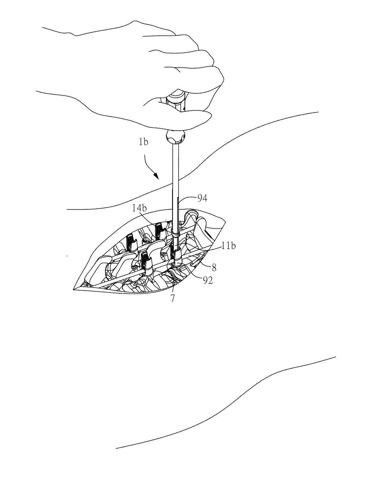
[0080]The surgeon can make the guiding hole 141c of the guide element 14c pass along the guiding unit 94 such that the operating element 11c approaches and settles on the outside of the receiver 92. Then the surgeon uses the spinal surgical instrument 1b (the pre-lock wrench) in the third embodiment in conjunction with the locking screw 7. The operating element 11b and the locking screw 7 are guided into the receiver 92 together for screwing the locking screw 7 within the receiver 92. In one aspect, the surgeon can use one hand to clasp the spinal surgical instrument 1b (the pre-lock wrench) to fix the rod 8 by locking the locking screw 7 and, meanwhile, uses the other hand to manipulate the spinal surgical instrument 1c (the anti-torque wrench) to stabilize the receiver 92 for preventing rotation caused by the action of screwing locking screw 7.

[0081]FIG. 8 is a schematic diagram of a spinal surgical instrument according to a fifth embodiment of the present invention. Please refer ...


PUM


Abstract

The present invention discloses a spinal surgical instrument and a method of guiding thereof. The spinal surgical instrument is operated with a precedent device. The precedent device includes at least one guiding unit. The spinal surgical instrument includes an operating element, an extending element, a handling element and a guide element. One end of the extending element connects to the operating element. The other end of the extending element connects to the handling element. The guide element is disposed on the extending element and includes at least one guide hole. The operating element is guided to the precedent device by the passing of the guide hole along the guiding unit.

Description

BACKGROUND OF THE INVENTION1. Field of the Invention[0001]The present invention relates generally to a surgical instrument, a method of guiding thereof and a system for bone stabilization, particularly to a spinal surgical instrument and a method of guiding thereof.2. Description of the Related Art[0002]The vertebral column is a major component of the central nervous system of the human body. Spinal disorders, especially in the lumbar region, often have a considerable impact on patients, causing pain, numbness, weakness, incontinence, dysuria, dyschezia, or other symptoms. The above symptoms are caused by a translocation between vertebral bodies oppressing the nerve or spinal cord. Due to different mechanisms, spinal disorders are clinically diagnosed as disc herniation, spondylolisthesis, spinal stenosis or degenerative scoliosis. When symptoms are severe, the discomfort of patients usually cannot be relieved by correction, and spinal surgery is required to reposition the vertebrae...

Claims


Application Information

Patent Timeline
Patent Type & Authority Applications(United States)
IPC IPC(8): A61B17/70A61B17/88
CPCA61B17/7001A61B17/708A61B17/8875A61B17/7083A61B17/8897A61B17/7061A61B17/7062A61B17/7074A61B17/7094A61B17/8805A61B17/885A61B2017/564A61B17/90A61B17/7032A61B17/7037A61B17/7091A61B17/8888A61B2090/037A61B2090/031A61B90/92
Inventor SU, YI-CHUNHUA, SHERWINHUANG, HSIANG-MINGLIANG, HUANG-CHIENLU, CHIEH-FENGCHEN, HUANG-CHI
Owner WILTROM
Why Eureka
Try Eureka