Liquid-dissolved gas separators

a separator and liquid-dissolved gas technology, applied in the direction of liquid degasification, separation process, membrane, etc., can solve the problems of affecting reducing the reliability of the fuel system

Active Publication Date: 2018-03-15
HAMILTON SUNDSTRAND CORP
View PDF0 Cites 18 Cited by
  • Summary
  • Abstract
  • Description
  • Claims
  • Application Information

AI Technical Summary

Benefits of technology

[0011]A method of making a separator for a liquid-dissolved gas separator includes fusing metallic particulate to define a separator liquid-facing surface and fusing particulate to define a separator vacuum-facing surface. The method includes connecting the liquid-facing surface with the vacuum-facing surface with the open pores and dimensioning the open pores with respective critical dimensions to selectively allow dissolved gas to pass through the open pores and prevent liquid from passing through the open pores of the separator. It is contemplated that dimensioning the pores can include the use of an additive manufacturing technique or a subsequent process, such as hot isostatic pressing.

Problems solved by technology

The coke precursors form coke or varnish depositions within internal fuel system structures, such as injectors, which may reduce the reliability of the fuel system.
Since such depositions can affect the reliability of the fuel system, some fuel systems employ deoxygenation structures for removing dissolved gases from fuel, such as Teflon or similar materials.

Method used


Image

  • Liquid-dissolved gas separators
  • Liquid-dissolved gas separators
  • Liquid-dissolved gas separators

Examples


Embodiment Construction

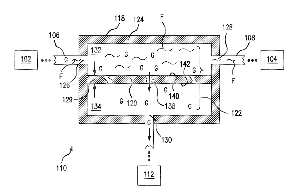
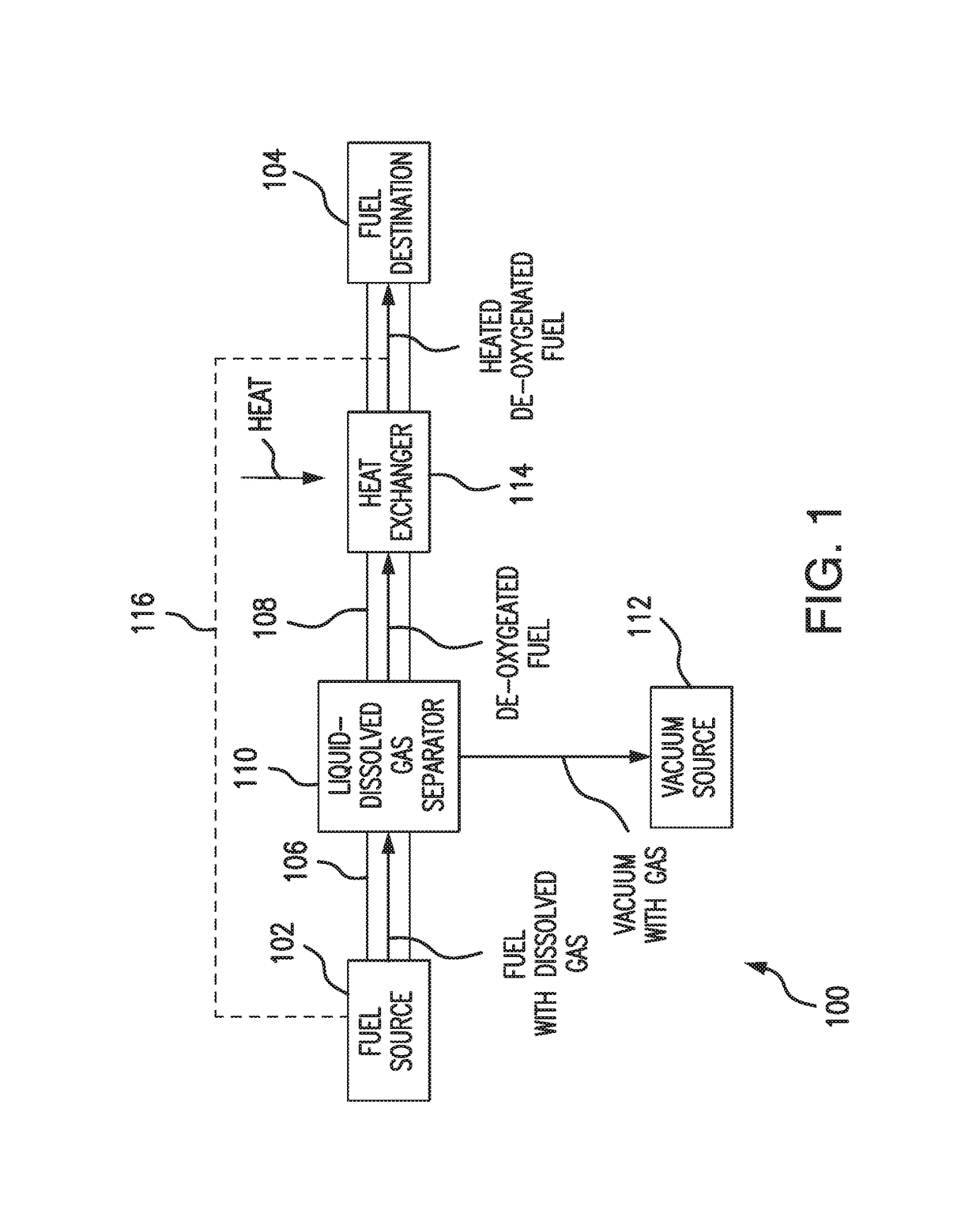
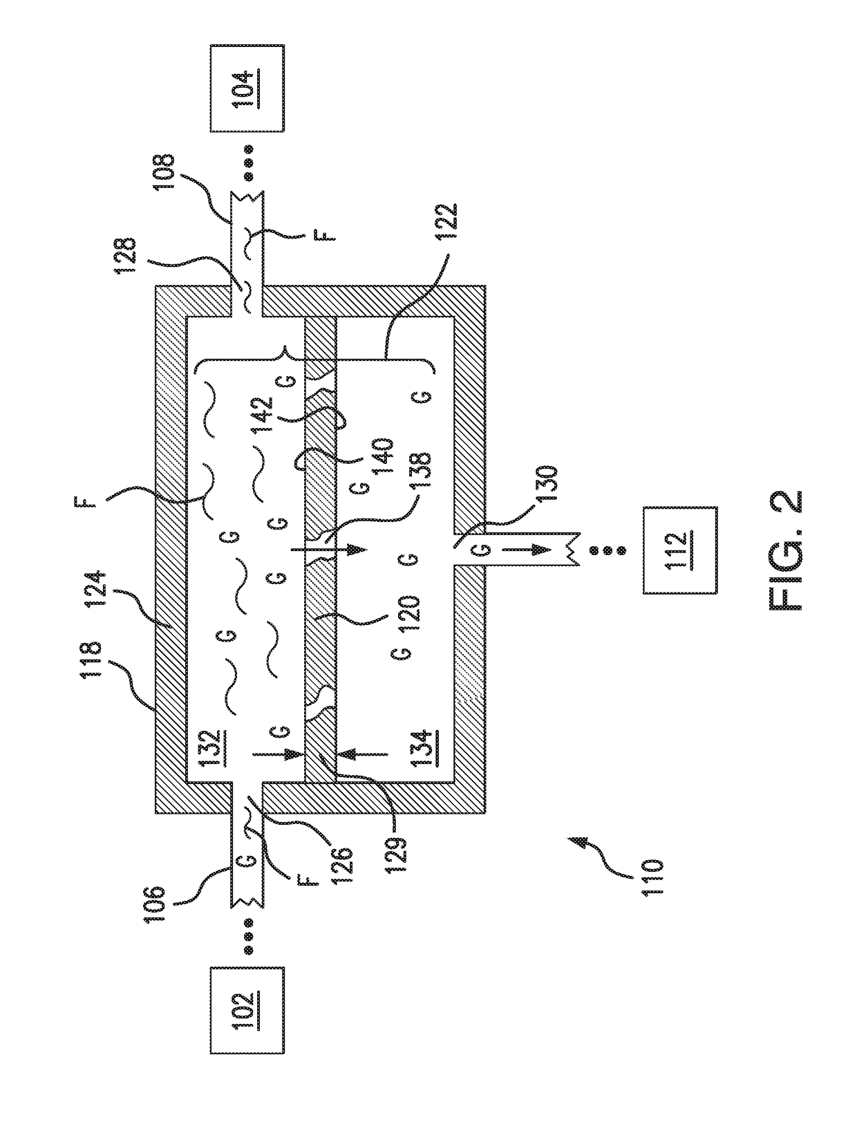
[0020]Reference will now be made to the drawings wherein like reference numerals identify similar structural features or aspects of the subject disclosure. For purposes of explanation and illustration, and not limitation, a partial view of an exemplary embodiment of a liquid-dissolved gas separator in accordance with the disclosure is shown in FIG. 1 and is designated generally by reference character 100. Other embodiments of liquid-dissolved gas separators, fuel system liquid-dissolved gas separators, and methods of making liquid-dissolved gas separators in accordance with the disclosure, or aspects thereof, are provided in FIGS. 2-6, as will be described. The systems and methods described herein can be used removing oxygen from liquid fuel, such as in gas turbine engine fuel systems, though present disclosure is not limited to gas turbine engines or to fuel systems in general.

[0021]Referring to FIG. 1, an exemplary fuel system, e.g. aircraft fuel system 100. Fuel system 100 includ...


PUM

PropertyMeasurementUnit
thicknessaaaaaaaaaa
thicknessaaaaaaaaaa
temperatureaaaaaaaaaa

Abstract

A liquid-dissolved gas separator includes a metallic separator. The separator has a plurality of open pores that connect a liquid-facing surface of the separator with an opposed vacuum-facing surface of the separator for separating dissolved gases from a liquid traversing the liquid-facing surface of the separator body.

Description

BACKGROUND OF THE INVENTION1. Field of the Invention[0001]The present disclosure relates to fuel systems, and more particularly for gas turbine engine fuel systems which route fuel through or in proximity to hot engine components.2. Description of Related Art[0002]Because of its relative abundance in the air of the atmosphere, relatively large quantities of oxygen, as well as nitrogen and other gases, readily dissolve into various liquid media. The presence of dissolved oxygen, in particular, in some liquids, such as hydrocarbon fuels for example, may support oxidation reactions that yield undesirable by-products.[0003]For instance, aircraft may employ fuel as coolant for various systems in the aircraft. When air-saturated fuel is heated, such as when traversing a hot engine components prior reaching the engine combustors, oxygen dissolved in the fuel can form coke precursor compounds. Such coking occurs most readily in the portions of the fuel system having high temperatures and / or...

Claims


Application Information

Patent Timeline
Patent Type & Authority Applications(United States)
IPC IPC(8): B01D19/00F02C7/22
CPCB01D19/0031F02C7/22B01D67/0041B01D71/022B64D37/34F05D2220/32B01D69/02B01D2325/02F23K2900/05082
Inventor RHODEN, WILLIAM E.
Owner HAMILTON SUNDSTRAND CORP
Why Eureka
Try Eureka