
Apparatus and method for heating a metallic vessel

a technology for heating apparatuses and metallic vessels, applied in lighting and heating apparatuses, manufacturing tools, furniture, etc., can solve the problems of difficult to achieve with external heating elements, require a greater amount of heat energy, and limit cooling, so as to reduce the electric current

Active Publication Date: 2018-03-15
CORNING INC
View PDF1 Cites 7 Cited by
  • Summary
  • Abstract
  • Description
  • Claims
  • Application Information

AI Technical Summary

Benefits of technology

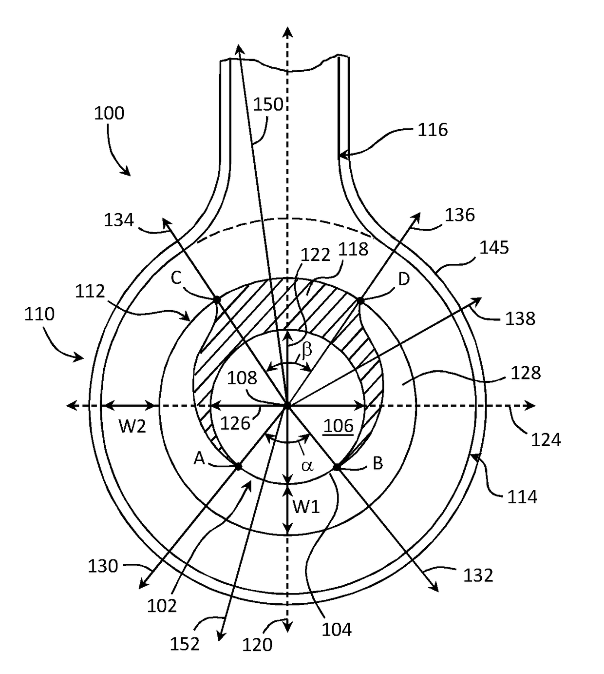
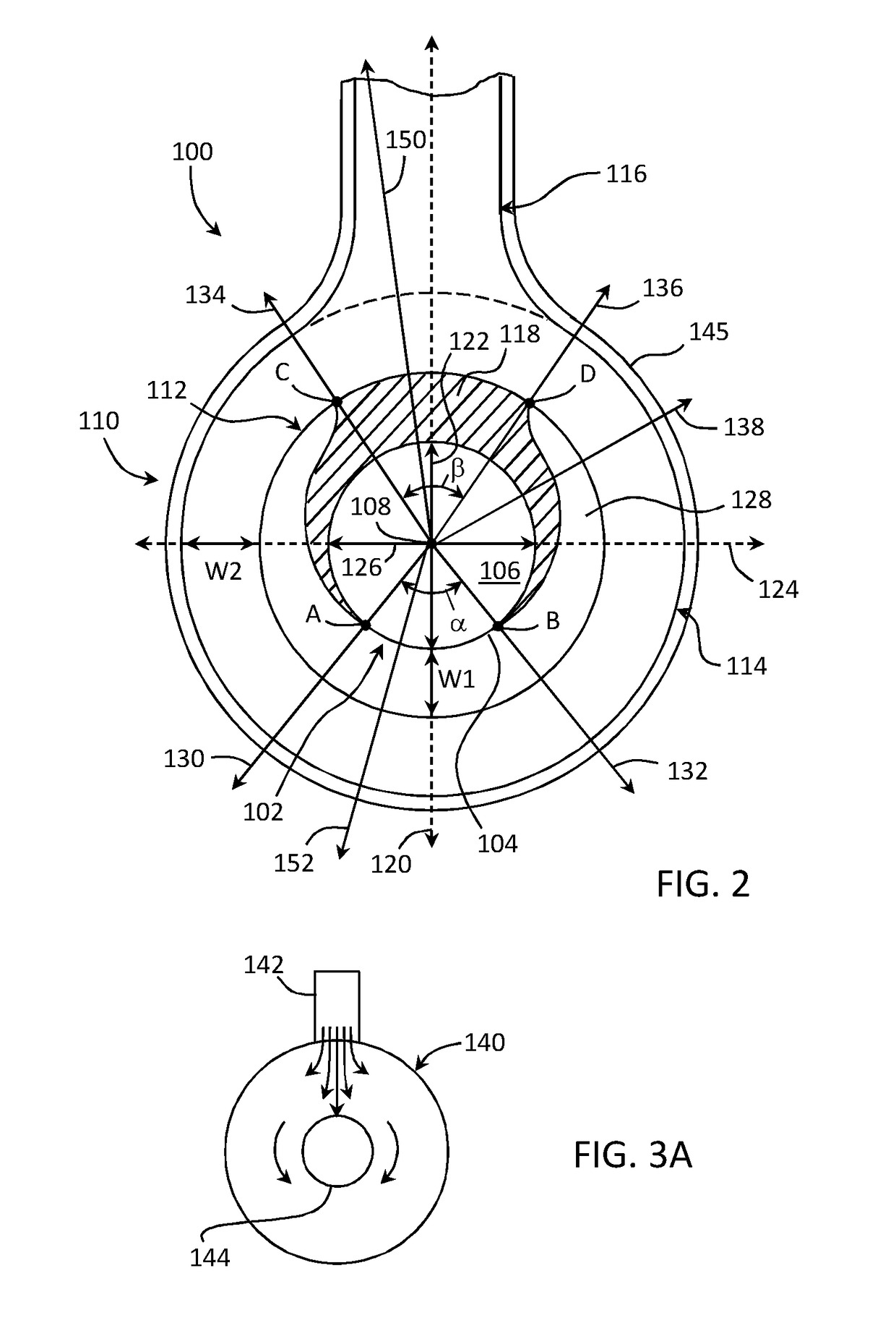
The invention is a flange design that reduces the concentration of electric current along the shortest conduction path between flanges and electrodes, which reduces the risk of electrical ar errections. This is achieved by directing electrical current towards the sides and bottom of the vessel, while avoiding the top of the vessel where the flange joins the vessel. The design has multiple parts in the first ring, which help to spread electric current and reduce the risk of injury or damage from high electric current concentrations.

Problems solved by technology

However, the cooling may be limited by the controlled addition of heat energy to prevent too rapid a cooling rate.
However, the increased flow volume may require a greater influx of heat energy to maintain processing temperatures.
At some point this becomes difficult to achieve with external heating elements.
Conventional flange designs may not adequately distribute the current around a perimeter of the vessel, often simply because electric current distribution within the flanges was not considered.
This can be particularly troublesome for non-circular vessels such as conduits with an oblong cross section.

Method used


Image

  • Apparatus and method for heating a metallic vessel
  • Apparatus and method for heating a metallic vessel
  • Apparatus and method for heating a metallic vessel

Examples


example 1

[0136]Modeling was performed using FLUENT software and software developed for electrical circuit analysis to evaluate an empty (no molten glass) conventional flange 800 shown in FIG. 10, configured for an oblong vessel 802 comprising a wall 804 enclosing an inner volume 806, with a flange design in accordance with the flange of FIG. 4, i.e. flange 200. Vessel wall 804 had a constant thickness of 40 mil (approximately 50.8 cm). Conventional flange 800 included a body portion 808 and an electrode portion 810 extending therefrom. Body portion 808 included a nickel outermost ring 810 with a thickness of 0.5 inches (1.27 cm), and two platinum-rhodium rings of different thickness—an innermost ring 812 with a constant thickness 80 mil (approximately 0.41 cm) and an intermediate ring 814 positioned between the outermost ring 810 and vessel 802 and with a constant thickness of 40 mil (approximately 0.20 cm). Both platinum-rhodium rings 812 and 814 extended completely around vessel 802. The v...

example 2

[0139]FIG. 11 shows modeled current density in flange 800 at three locations along a length of a vessel (conduit) with a supplied electric current of 12,000 amps / mm2 compared with the electric current density for flange 200. The flanges 200 and 800 were again paired with an identical respective flanges on an oblong vessel (conduit) having a minor axis of 9 inches (approximately 22.9 cm) and a major axis of 30 inches (76.2 cm), with a spacing of 60 inches (152.4 cm) between the paired flanges. Current density was calculated at the top of the vessel, at the major axis (edge), and at the bottom of the vessel. Conventional flange 800 included a body portion 808 and an electrode portion 810 extending therefrom. Body portion 808 included a nickel outermost ring 810 with a thickness of 0.5 inches (1.27 cm), and two platinum-rhodium rings of different thickness—an innermost ring 812 with a constant thickness 80 mil (approximately 0.41 cm) and an intermediate ring 814 positioned between the ...


PUM

PropertyMeasurementUnit
Thicknessaaaaaaaaaa
Shapeaaaaaaaaaa
Perimeteraaaaaaaaaa

Abstract

Disclosed is an apparatus and method of making molten glass. The apparatus includes a vessel for conveying the molten glass and at least one flange configured to supply an electric current to the vessel through the flange, the flange including a first ring extending completely around the vessel in a closed loop, the first ring comprising a first portion including a first thickness and a second portion including a second thickness different from the first thickness, wherein the first portion and the second portion overlap in a plane of the flange such that at least a portion of the first portion is positioned between at least a portion of the second portion and the vessel wall, and neither the first portion nor the second portion extends completely around the vessel. Also disclosed is a method of making glass using the disclosed flange.

Description

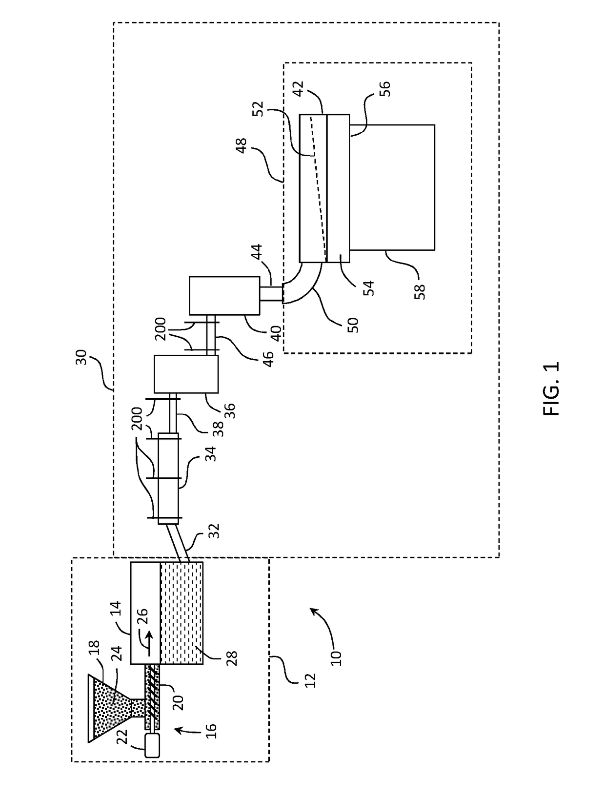
CROSS-REFERENCE TO RELATED APPLICATIONS[0001]This application claims the benefit of priority under 35 U.S.C. §119(e) of U.S. Provisional Application Ser. No. 62 / 136863 filed on Mar. 23, 2015, the content of which is incorporated herein in its entirety by reference.BACKGROUNDField[0002]The present disclosure is directed to an apparatus for heating a metallic vessel, and more particularly an apparatus for heating a metallic vessel configured to convey a material, and the material contained therein, by direct electrical heating of the vessel. The material may be, for example, molten glass.Technical Background[0003]The manufacture of glass on a commercial scale is typically carried out within a refractory ceramic melting furnace wherein raw materials (batch) are added to the melting furnace and heated to a temperature at which the batch undergoes chemical reactions to produce the molten glass. Several methods of heating the batch can be used, including gas-fired burners, an electric cur...

Claims


Application Information

Patent Timeline
IPC IPC(8): C03B5/435C03B5/02
CPCC03B5/435C03B5/02C03B5/033C03B7/07C03B7/098H05B3/03F27D99/0001F27D99/0006F27D99/0033
Inventor DE ANGELIS, GILBERTHE, CHUNHONG CHELSIE
Owner CORNING INC
Learn More