

Spectrally selective solar absorbing coating and a method for making it
- Summary
- Abstract
- Description
- Claims
- Application Information
AI Technical Summary
Benefits of technology
Problems solved by technology
Method used
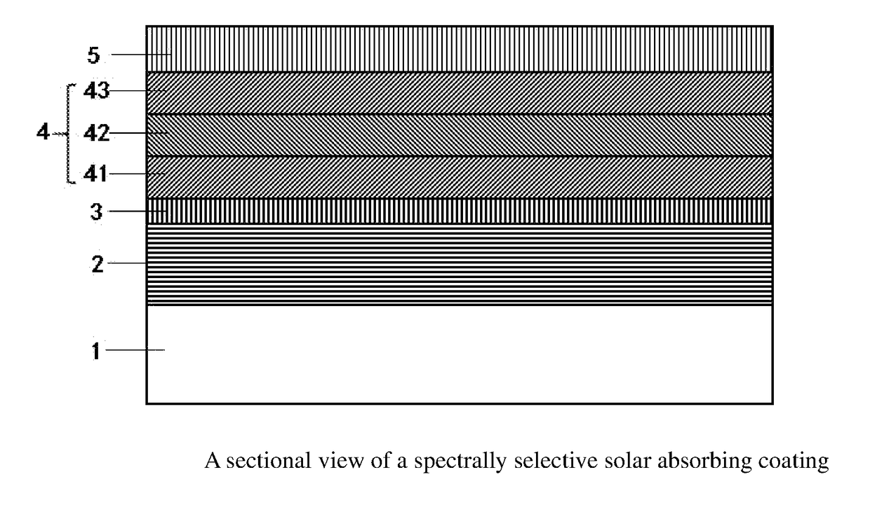
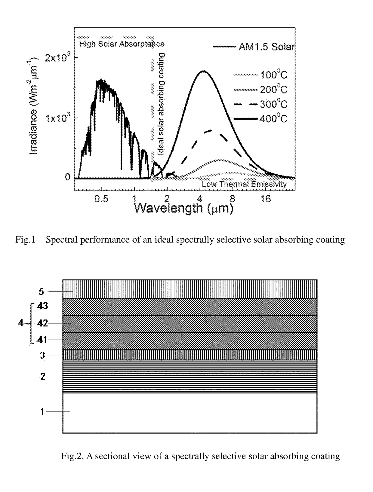
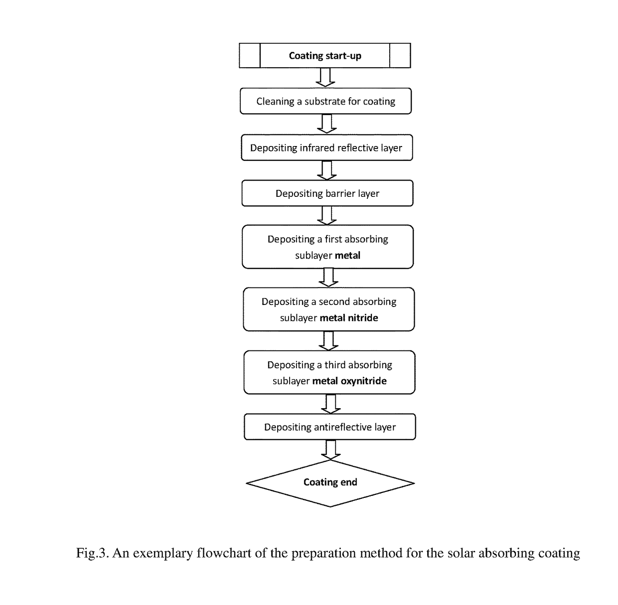
Image

Examples
example 1
[0061]The specific steps of the preparation process of the above example 1 on glass substrates are as following:
[0062]1) Cleaning of the glass pane: First, A glass pane was ultrasonically cleaned in a neutral detergent solution and thereafter rinsed in deionized water. Then, the glass pane was placed in the entrance chamber of the magnetron sputtering equipment and performed second cleaning step, using an RF plasma source to bombard the glass pane surface. The process parameters were as following: RF source sputtering power was 200 w, flow rate of working gas Ar (purity 99.99%), was 45 sccm, the working pressure was 9.8×10⁻² mTorr, and sputtering time was 360 s.
[0063]2) The cleaned glass substrate was passed from the entrance chamber to the sputtering chamber of the deposition equipment. The base pressure of the sputtering chamber was lower than 6×10⁻⁶ Torr.
[0064]3) Forming the infrared reflective layer Al on the glass substrate: A metal Al target (purity 99.7%) was magnetron sputte...
example 2
[0072]Example 2: The coating processing was same as that of the example 1, except of adding the barrier layer CrNx between IR reflective Al and absorbing sublayer metal Cr. The processing parameters of the barrier layer CrNx were as follows: the sputtering power was 1500 w, the working pressure was 3 mTorr, the working gas Ar (purity 99.99%) flow rate was 50 sccm, the working gas N2 (purity 99.99%) flow rate was 50 sccm, the substrate moving speed was 2 m / min and the substrate was moved back and forth 3 times under the Cr target, and the substrate temperature was room temperature.
[0073]The multilayer stack, example 2 was then heated in air at 250° C. for 370 hr.
example 3-15
[0074]The coating processing parameters were same as the above detailed description for example land example 2, except of the coating processing of the composite absorbing layer.
[0075]1) The substrate moving speed and the number of the passes were determined according to the thickness of the film being sputtered.
[0076]2) When coating CrNx layer, the flow rate of working gas N2 was chosen randomly between 50 sccm and 100 sccm.
[0077]3) When coating CrNyOz layer, the flow rate of working gas O2 was chosen randomly between 10 sccm and 50 sccm.
[0078]For the examples in the present embodiment of the invention, the 0.3-2.5 μm reflective spectra were measured using a spectrophotometer at room temperature, which can be used to calculated the absorbing spectra in accordance to spectral absorptance α being expressed in terms of total reflectance ρ for opaque materials, α=100−ρ(%). The solar absorptance was obtained by numerical integration of the above absorbing curves over the solar distribut...
PUM
| Property | Measurement | Unit |
|---|---|---|
| Thickness | aaaaa | aaaaa |
| Thickness | aaaaa | aaaaa |
| Thickness | aaaaa | aaaaa |
Abstract
Description
Claims
Application Information