Vehicle and method for controlling the same

a technology for vehicles and methods, applied in mechanical devices, transportation and packaging, gear slippage, etc., can solve problems such as possible loss of fuel efficiency, decrease in the amount of regeneration, and belt slippage, and achieve the effect of improving fuel efficiency and enhancing shift responsiveness

Active Publication Date: 2018-03-22
JATCO LTD +1
View PDF0 Cites 3 Cited by
  • Summary
  • Abstract
  • Description
  • Claims
  • Application Information

AI Technical Summary

Benefits of technology

[0003]With a belt-type continuously variable transmission, a primary pressure is lowered at a downshift to increase a differential pressure between the primary pressure and a secondary pressure, ensuring improving a shift speed. For example, in the case where a sudden braking intending a vehicle stop is performed, this allows easily shifting a speed ratio to a Lowest speed ratio, namely, a maximum speed ratio until the vehicle stop, thereby ensuring enhancing vehicle startability. Accordingly, to downshift the belt-type continuously variable transmission, lowering the primary pressure as much as possible is desirable in terms of shift responsiveness.
[0006]The present invention has been made in consideration of such technical problem. The object is to provide a vehicle and a method for controlling the vehicle that allow both an improvement in fuel efficiency by regeneration by a motor-generator and shift responsiveness even at a sudden braking for downshift.
[0010]With these aspects, since the target hydraulic pressure for the secondary pressure is set on the basis of the first braking capacity during the downshift, a belt sandwiching force according to the first braking capacity can be generated at the secondary pulley. Since the belt is pulled from the primary pulley side to the secondary pulley side according to this, the belt sandwiching force according to the first braking capacity can be generated alto at the primary pulley. Accordingly, with these aspects, the belt does not slip during the sudden braking.
[0011]Accordingly, these aspects achieve the improvement in fuel efficiency by the regeneration by the motor-generator even during the sudden braking.
[0012]With these aspects, the target hydraulic pressure for the primary pressure is set on the basis of a primary guaranteed capacity including the second braking capacity set lower than the first braking capacity. Therefore, lowering the primary pressure allows increasing a differential pressure between the primary pressure and the secondary pressure. Accordingly, these aspects also ensure enhancing shift responsiveness.

Problems solved by technology

In view of this, when the vehicle that includes the belt-type continuously variable transmission and the motor-generator lowers the primary pressure for the downshift, a belt sandwiching force at the primary pulley lowers, possibly resulting in a belt slip.
However, since the amount of regeneration lowers, fuel efficiency is possibly lost.

Method used


Image

  • Vehicle and method for controlling the same
  • Vehicle and method for controlling the same
  • Vehicle and method for controlling the same

Examples


first embodiment

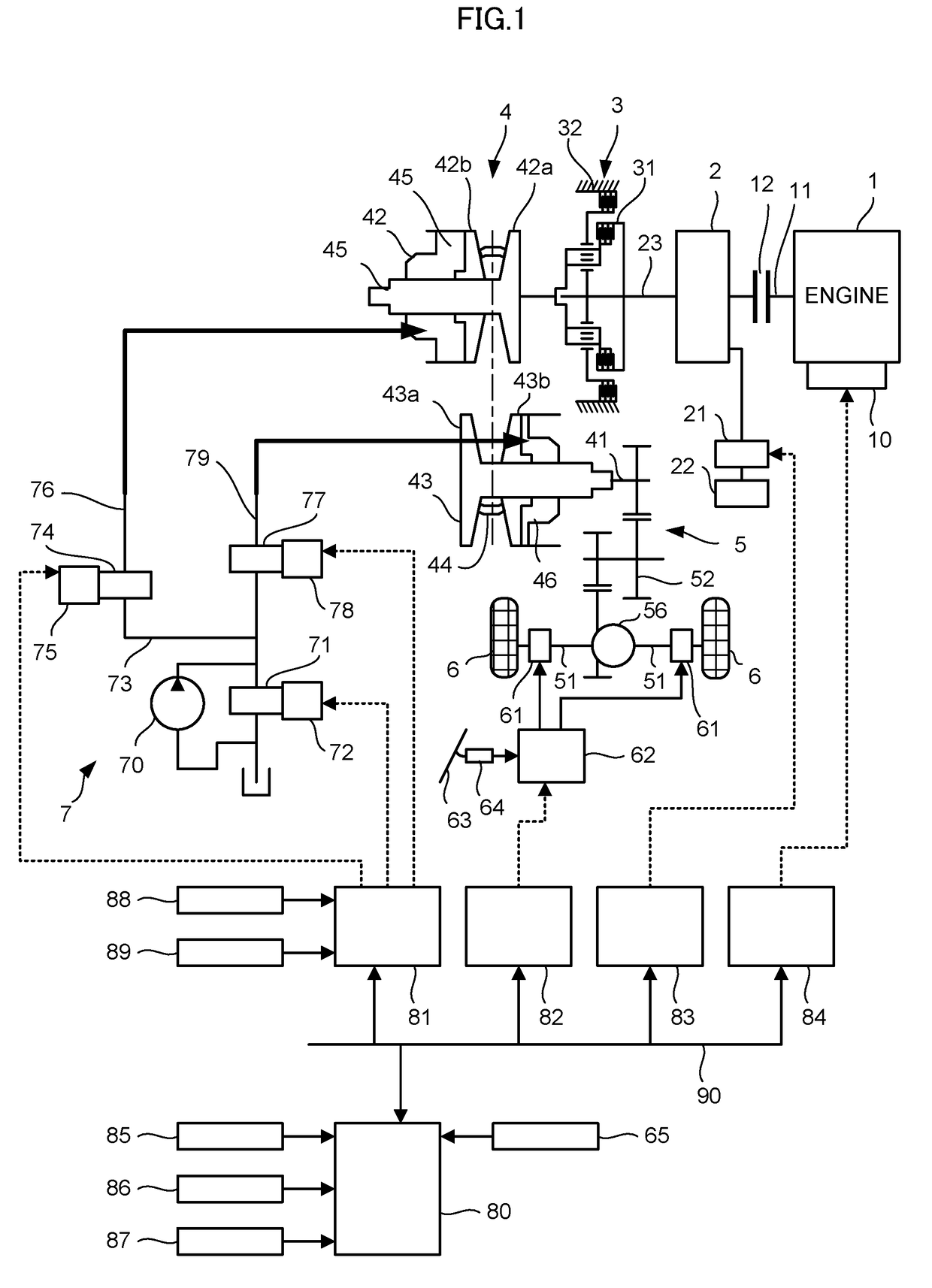
[0023]FIG. 1 is a schematic configuration diagram of a vehicle of this embodiment. The vehicle includes an engine 1 and a motor-generator 2 as a driving source. An output rotation of the engine 1 or the motor-generator 2 is transmitted to driving wheels 6 via a steering reverser mechanism 3, a transmission 4, and a final reduction gear 5.

[0024]The engine 1 includes a control-target unit 10 as a target for control to control the engine 1. The control-target unit 10, for example, includes a fuel injection valve and a throttle valve. The control-target unit 10 operates the engine 1 at a desired torque on the basis of a command from an engine control unit 84 to rotate an output shaft 11. Between the engine 1 and the motor-generator 2, a first clutch 12 is disposed. The first clutch 12 intermits a rotation between the engine 1 and the motor-generator 2.

[0025]The motor-generator 2 is driven by electric power output from an inverter 21. The motor-generator 2 has regenerative electric power...

second embodiment

[0131]The vehicle of this embodiment is configured similarity to the vehicle of the first embodiment except for configurations of the CVTCU 81 further described below.

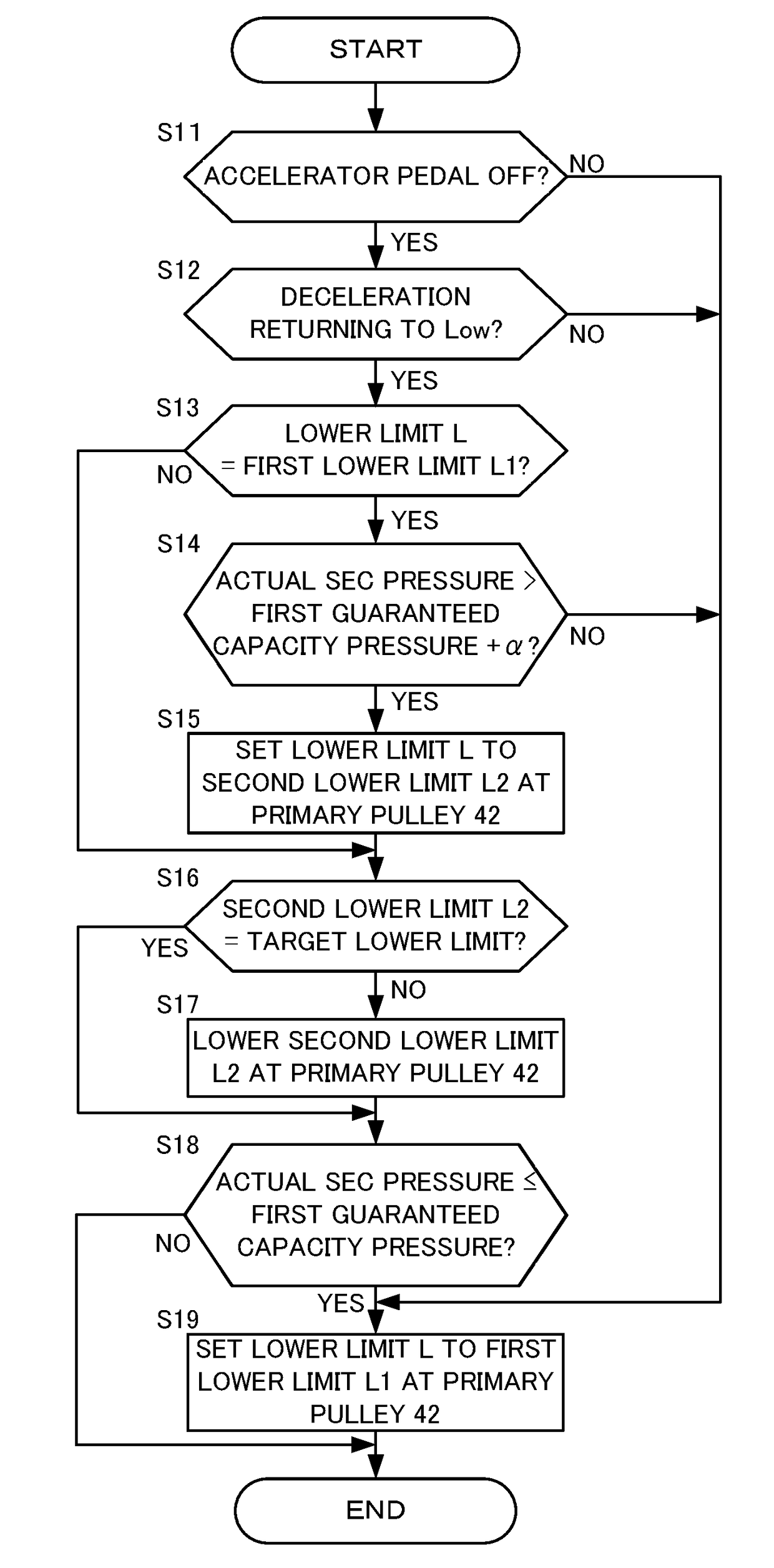
[0132]FIG. 8 is a drawing illustrating one example of the control performed by the CVTCU 81 and one example of the setting method for the lower limit L at the secondary pulley 43 by a flowchart. The CVTCU 81 can repeatedly perform the processes of this flowchart by minute time.

[0133]At Step S21 and Step S22, as illustrated in the drawing, the processes similar to Step S11 and Step S12 are performed.

[0134]The negative determination at Step S21 or Step S22 advances the process to Step S24. In this case, the CVTCU 81 sets the SEC pressure lower limit to a first capacity guaranteed pressure.

[0135]The positive determinations at Step S21 and Step S22 advance the process to Step S23. In this case, the CVTCU 81 sets the SEC pressure lower limit to a sum of the first capacity guaranteed pressure and a predetermined value β. The...


PUM


Abstract

The present invention is related to a vehicle including a motor-generator, a transmission, a shift hydraulic control unit, and a CVT control unit (CVTCU). When a downshift of the transmission is performed without an acceleration request from a driver, the CVTCU sets a pulley thrust at a secondary pulley on the basis of a first lower limit as a lower limit, which is a sum of a fundamental thrust and a first correction thrust. The CVTCU also sets a pulley thrust at a primary pulley on the basis of a second lower limit as a lower limit, which is a sum of the fundamental thrust and a second correction thrust.

Description

TECHNICAL FIELD[0001]The present invention relates to a vehicle and a method for controlling the same.BACKGROUND ART[0002]WO2011 / 145222A discloses a technique that temporarily lowers an instructed pressure of a primary pressure at a start of downshift of a belt-type continuously variable transmission enhances shift responsiveness.SUMMARY OF INVENTION[0003]With a belt-type continuously variable transmission, a primary pressure is lowered at a downshift to increase a differential pressure between the primary pressure and a secondary pressure, ensuring improving a shift speed. For example, in the case where a sudden braking intending a vehicle stop is performed, this allows easily shifting a speed ratio to a Lowest speed ratio, namely, a maximum speed ratio until the vehicle stop, thereby ensuring enhancing vehicle startability. Accordingly, to downshift the belt-type continuously variable transmission, lowering the primary pressure as much as possible is desirable in terms of shift re...

Claims


Application Information

Patent Timeline
Patent Type & Authority Applications(United States)
IPC IPC(8): F16H61/662B60K6/543B60W20/00F16H61/30F16H9/18
CPCF16H61/66272B60K6/543B60W20/00F16H61/30F16H9/18B60Y2200/92B60Y2300/18125Y10S903/945Y10S903/918F16H2059/147B60L7/14B60L15/20B60W10/10B60W30/18127B60W10/08B60W10/18B60W30/18063B60W2540/10B60W2540/12B60W2720/30Y02T10/72B60W10/101B60W20/14F16H61/02
Inventor IWASA, HIROKIMIYAISHI, HIRONORIRYU, SUNGPILIZUMI, TETSUYA
Owner JATCO LTD
Why Eureka
Try Eureka