
Lidar System Noise Reduction Combining Circular Polarization Laser Output with Photon Sieve Optics in the Receiver

a technology of circular polarization laser and receiver, applied in the field oflidar systems, can solve problems such as various drawbacks of known methods for increasing snr

Active Publication Date: 2018-03-22
NAT INST AEROSPACE ASSOC +1
View PDF2 Cites 6 Cited by
  • Summary
  • Abstract
  • Description
  • Claims
  • Application Information

AI Technical Summary

Benefits of technology

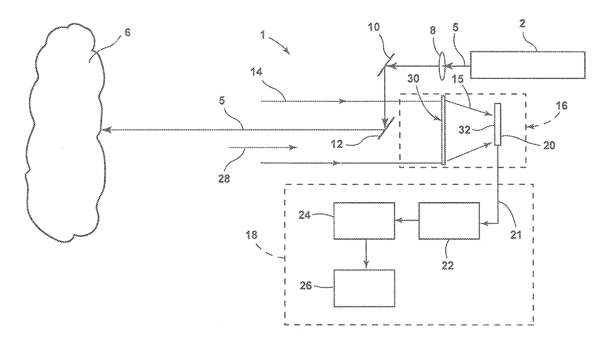
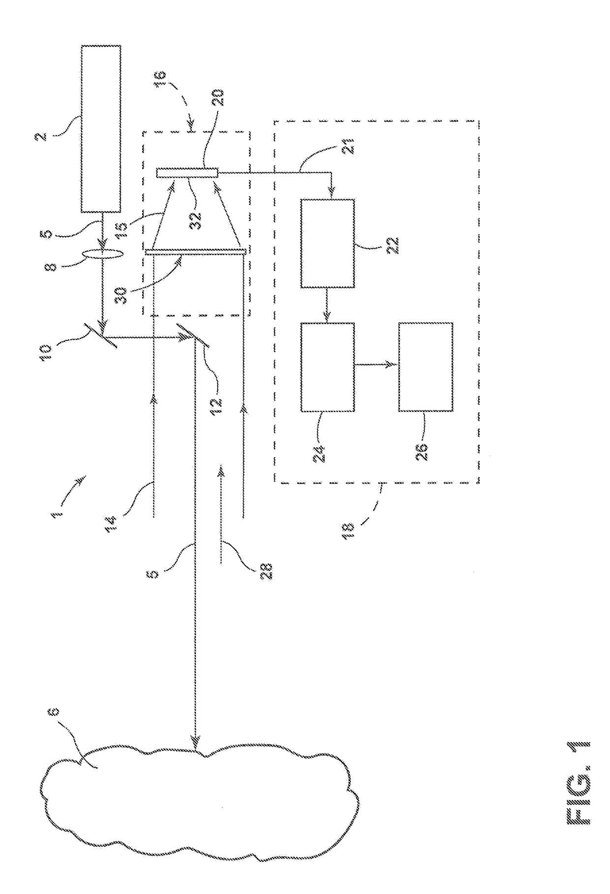
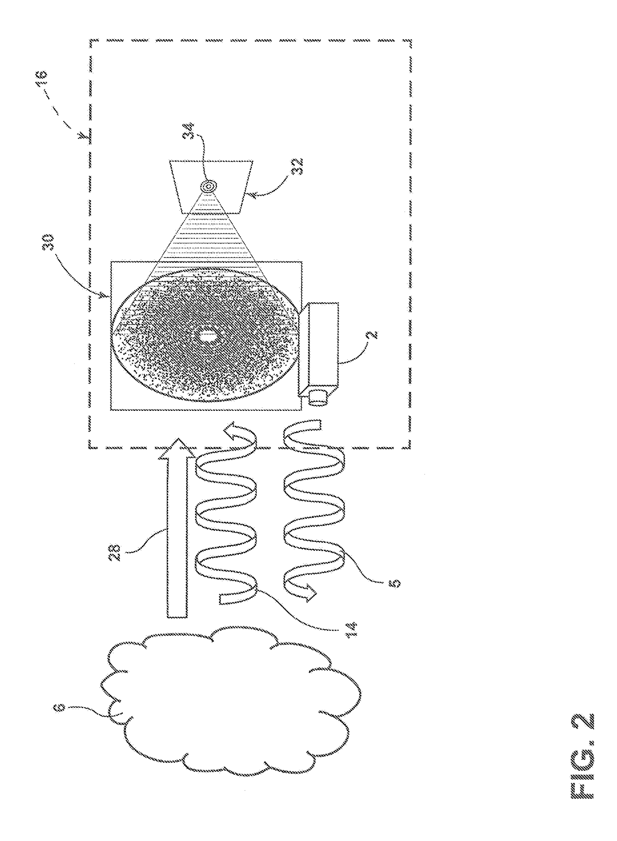
The present patent is related to a lidar system that uses a laser to generate a beam of light that is then reflected back to the system. A unique feature of this system is that it also includes a photon sieve that creates a ring pattern on the surface that is focused by the laser. This ring pattern is made up of polarized light that is transmitted by the laser and reflected back to the system. The photon sieve causes stray light that is not polarized to create a central region that is distinct from the ring pattern. This technology helps to separate out the stray light and ensure that the received signals are accurate.

Problems solved by technology

However, known methods to increase SNR may suffer from various drawbacks.

Method used


Image

  • Lidar System Noise Reduction Combining Circular Polarization Laser Output with Photon Sieve Optics in the Receiver
  • Lidar System Noise Reduction Combining Circular Polarization Laser Output with Photon Sieve Optics in the Receiver
  • Lidar System Noise Reduction Combining Circular Polarization Laser Output with Photon Sieve Optics in the Receiver

Examples


Embodiment Construction

[0009]For purposes of description herein, the terms “upper,”“lower,”“right,”“left,”“rear,”“front,”“vertical,”“horizontal,” and derivatives thereof shall relate to the disclosure as oriented in FIG. 1. However, it is to be understood that the disclosure may assume various alternative orientations and step sequences, except where expressly specified to the contrary. It is also to be understood that the specific devices and processes illustrated in the attached drawings, and described in the following specification, are simply exemplary embodiments of the concepts defined in the appended claims. Hence, specific dimensions and other physical characteristics relating to the embodiments disclosed herein are not to be considered as limiting, unless the claims expressly state otherwise.

[0010]With reference to FIG. 1, a lidar system 1 includes a light source such as a laser 2 that produces an output signal such as laser beam 4. As discussed in more detail below, the laser beam may comprise a...


PUM


Abstract

A lidar system includes an optical transmitter having a laser light source that is configured to generate a beam of light that is azimuthally polarized or has Orbital Angular Momentum (OAM). The lidar system further includes an optical receiver having an optical sensor defining a focal plane. A photon sieve is configured to produce a ring pattern on the focal plane corresponding to a laser return signal. The ring pattern comprises azimuthally polarized or Orbital Angular Momentum (OAM) light that is transmitted by the transmitter and reflected towards the receiver. The photon sieve is also configured to cause stray light that is not polarized to produce a central region at the center of the ring pattern that is distinct from the ring pattern.

Description

STATEMENT REGARDING FEDERALLY SPONSORED RESEARCH OR DEVELOPMENT[0001]The invention described herein was made in the performance of work under a NASA contract and by employees of the United States Government and is subject to the provisions of Public Law 96-517 (35 U.S.C. § 202) and may be manufactured and used by or for the Government for governmental purposes without the payment of any royalties thereon or therefore. In accordance with 35 U.S.C. § 202, the contractor elected not to retain title.BACKGROUND OF THE INVENTION[0002]Various types of lidar systems have been developed. Known space-based lidars typically require a telescope with sufficient area to increase the return signal on the detector to levels above the noise floor of the detectors. Two major drivers of the signal-to-noise ratio (SNR) on the detectors are the laser output energy and the round trip distance traveled by the laser signal. The SNR on the detectors can be increased by increasing the telescope reflector are...

Claims


Application Information

Patent Timeline
Patent Type & Authority Applications(United States)
IPC IPC(8): G01S7/499G01S17/02
CPCG01S17/02G01S7/499G01S7/4816
Inventor SUN, WENBOHU, YONGXIANGMACDONNELL, DAVID G.
Owner NAT INST AEROSPACE ASSOC
Learn More