Apparatus and Method of Reinforcing a Conduit or Vessel

a technology of pipe reinforcement and apparatus, applied in the field of pipelines, can solve the problems of reducing the service life of pipes, and reducing the provision for use inside pipes or vessels, so as to facilitate the reinforcing of pipes, reduce the down-time of pipes, and install quickly

Inactive Publication Date: 2009-12-24
EHSANI MOHAMMAD R
View PDF13 Cites 22 Cited by
  • Summary
  • Abstract
  • Description
  • Claims
  • Application Information

AI Technical Summary

Benefits of technology

[0013]The present method facilitates the reinforcing of pipes from the inside and results in a reinforcement of the pipe that is substantially water-tight along its length, strong, light-weight, relatively easy-to-install, and that is installed quickly, reducing down-time of the pipe. The composite laminate material of the present method is easy to fabricate, even when customization is required. Further, the composite laminate of the present method is easy to tr

Problems solved by technology

However, the liners that are specified, e.g. felt, are only intended to be resin-absorbing media, such that the liners absorb relatively large quantities of resins.
There is no mention of strengthening a pipe in any of these patents, nor will the mixture of felt and resin provide any substantial strength to the pipe.
Further, such pre-formed sections must be small enough to fit within

Method used


Image

  • Apparatus and Method of Reinforcing a Conduit or Vessel
  • Apparatus and Method of Reinforcing a Conduit or Vessel
  • Apparatus and Method of Reinforcing a Conduit or Vessel

Examples


example 1

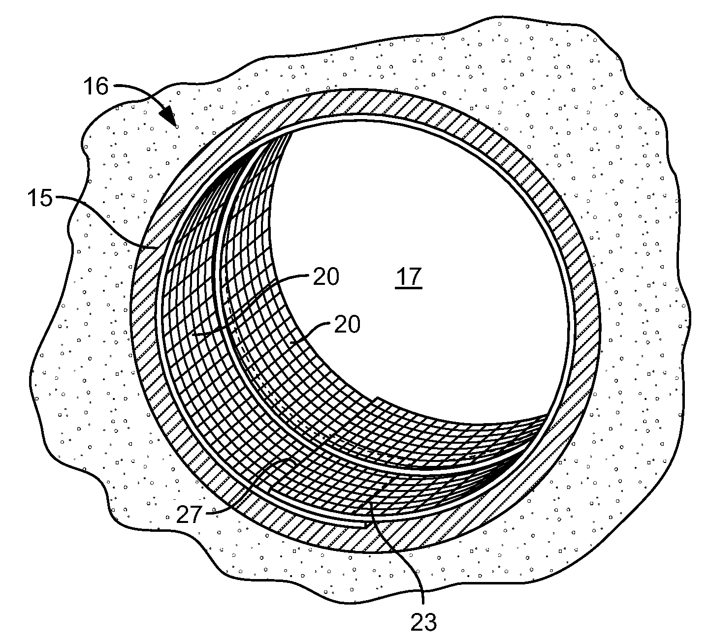
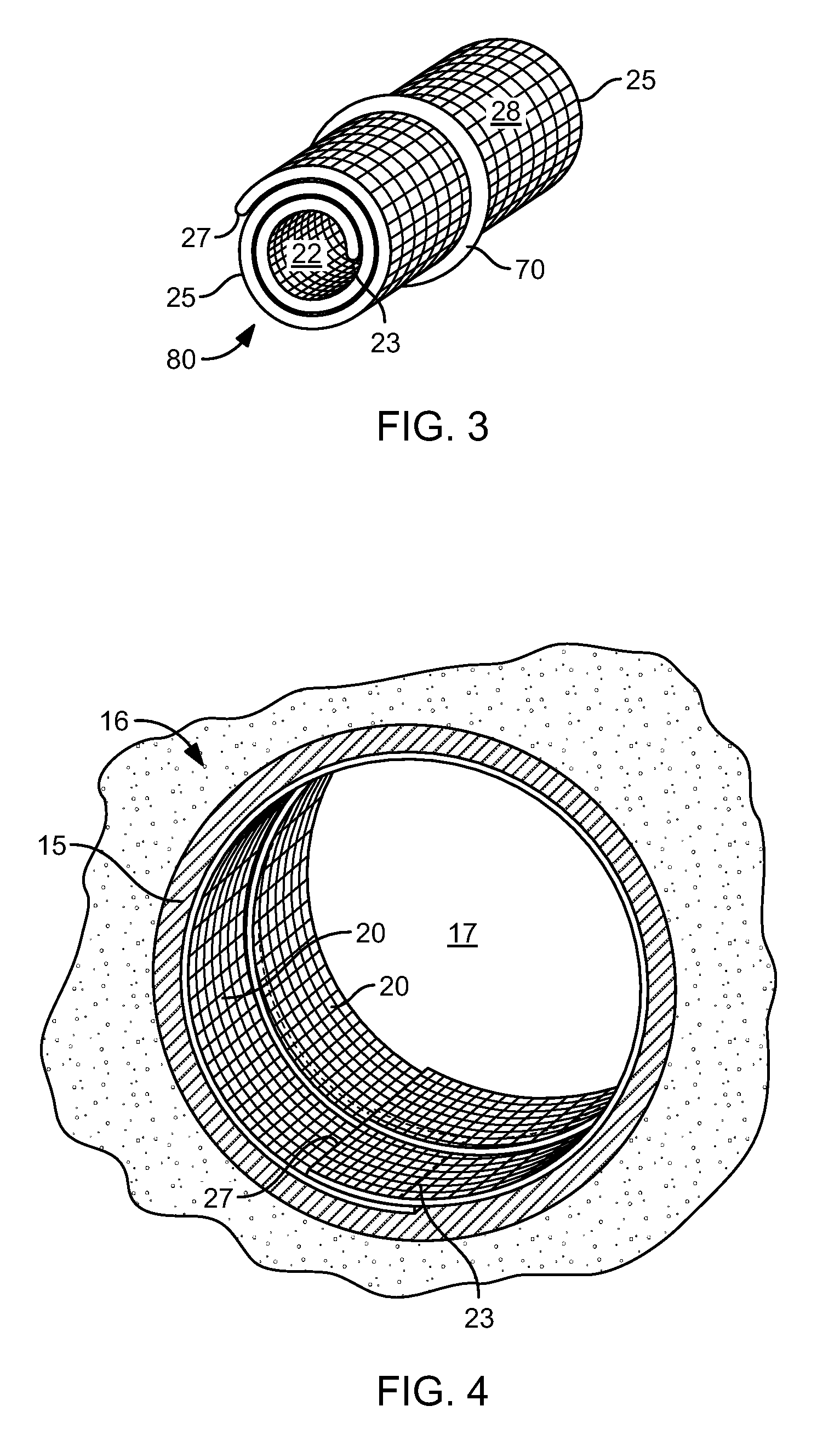
[0038]It is assumed that a concrete pipe 16 having an internal diameter of D=60 inches is subjected to an internal pressure of 25 psi. It is further assumed that considering factors of safety, the pipe 16 has to be designed to withstand a pressure of p=50 psi. It is further assumed that due to corrosion and other damage, the strength of the pipe 16 has diminished so much that it can be negligible, so that the new web 10 must resist the entire pressure of 50 psi. Using the relationships known to those skilled in design of pressure vessels, the force in the hoop direction is given by:

T=p D / 2=50 psi*(60 inch) / 2=1500 pounds per inch length of the pipe 16.

[0039]Assuming that the pipe 16 is being strengthened with laminates 20 placed inside the pipe 16 in the hoop direction (not spirally), the force of 3000 pounds is resisted by the fibers 30 positioned along the longitudinal direction of the laminate 20. Thus a laminate 20 with a minimum strength of 1500 pounds per inch width of the lami...

example 2

[0040]Assume that the pipe 16 of Example 1 is further subjected to axial forces such that a force of 200 pounds per inch is required along the axis of the pipe 16. This force could be due to flexural bending of the pipe, for example. In this case, the web 10 is constructed such that the longitudinal fibers 30 provide the previously-given strength of 1500 pounds per inch width of laminate 20 and the cross-linking or transverse fibers 40 provide a strength of 200 pounds per inch width of laminate 20 laterally. In placement of each laminate 20 for this example, the overlap 100 along the length of the pipe 16 must be large enough to allow the development of 200 pounds per inch of laminate 20. Similar to Example 1, the overlap 120 at the end of the band must also be large enough to allow the development of 1500 pounds per inch width of the web 10.

example 3

[0041]Assume that the pipe 16 of Example 1 is to be reinforced with a web 10 that has most of its fibers 35 oriented along the longitudinal axis. Each laminate 20 is assumed to be w=50 inches wide and installed on the pipe surface 15 in a spiral manner (FIG. 6) with an overlap length 100 of m=4 inches wide. The orientation of each laminate 20 results in a small reduction in the effective forces in the hoop direction. The efficiency factor can be calculated as:

R=πD / √[S2+(πD)2]

where S=w−m=50−4=46 inches.

[0042]This results in R=0.97, which means that in order to achieve a 1500 pounds per inch strength in the hoop direction, the web 10 must have a strength along its longitudinal axis at least equal to 1500 / 0.97=1544 pounds per inch width.


PUM

PropertyMeasurementUnit
Thicknessaaaaaaaaaa
Lengthaaaaaaaaaa
Structureaaaaaaaaaa

Abstract

A web for reinforcing the wall of a vessel or conduit, and methods of installation therein, is disclosed. The vessel or conduit is any structure that has a concave or arched inner surface. The web is comprised of an elongated composite laminate that has a fabric layer with a plurality of fibers embedded into a cured resin matrix. When cured on a curing surface, the composite laminate retains an elastic memory of the curing surface such that the composite laminate is substantially self-supporting against the inside surface of the wall due to its elastic memory. In use, a tack coat of epoxy with viscosities ranging from low to high, or gel epoxy, is applied to at least a portion of the bottom side of the laminate, which is then applied to the inside surface of the wall so as to reinforce the wall. Multiple such composites may be applied to the wall in turn in a ring pattern or in a spiral pattern, overlapping at least one recently applied composite to form a water-tight seal within the conduit and to reinforce the conduit.

Description

CROSS-REFERENCE TO RELATED APPLICATIONS[0001]This application claims the benefit of U.S. Provisional Patent Application 61 / 132,311, filed on Jun. 18, 2008, and incorporated herein by reference.STATEMENT REGARDING FEDERALLY SPONSORED RESEARCH AND DEVELOPMENT[0002]Not Applicable.NOTICE OF COPYRIGHTS AND TRADE DRESS[0003]A portion of the disclosure of this patent document contains material which is subject to copyright protection. This patent document may show and / or describe matter which is or may become trade dress of the owner. The copyright and trade dress owner has no objection to the facsimile reproduction by any one of the patent disclosure as it appears in the Patent and Trademark Office patent files or records, but otherwise reserves all copyright and trade dress rights whatsoever.FIELD OF THE INVENTION[0004]This invention relates to pipelines, and more particularly to improved pipeline reinforcement devices and methods.DISCUSSION OF RELATED ART[0005]There are many methods for...

Claims


Application Information

Patent Timeline
IPC IPC(8): B29C65/52D03D15/00
CPCB29C63/30Y10T156/10B29K2063/00B29K2067/00B29K2075/00B29K2105/06B32B5/26B32B5/28B32B27/04B32B27/12B32B27/38D03D15/00D10B2101/06D10B2101/08D10B2101/12D10B2101/20D10B2321/021D10B2331/021D10B2401/063D10B2505/02F16L55/1655F16L55/1656B29C63/32B32B5/024B32B5/24B32B7/12B32B27/28B32B1/08B32B3/12B32B2255/02B32B2255/26B32B2260/021B32B2260/046B32B2262/0253B32B2262/0269B32B2262/101B32B2262/103B32B2262/105B32B2262/106B32B2307/514B32B2307/54B32B2307/714B32B2307/7265B32B2597/00B32B2607/00Y10T442/3008D03D15/573
Inventor EHSANI, MOHAMMAD R.
Owner EHSANI MOHAMMAD R
Why Eureka
Try Eureka