Resistorless precharging

a resistor and precharging technology, applied in the direction of ac-dc conversion, electrical equipment, efficient power electronics conversion, etc., can solve the problems of increasing space requirements, increasing manufacturing costs, and needing resistors to limit the charge current, so as to reduce space requirements, reduce design constraints, and simplify the effect of design

Active Publication Date: 2018-03-22
DELTA ELECTRONICS (THAILAND) PUBLIC CO LTD
View PDF8 Cites 7 Cited by
  • Summary
  • Abstract
  • Description
  • Claims
  • Application Information

AI Technical Summary

Benefits of technology

The invention is a converter arrangement that simplifies the design and reduces space requirements and manufacturing costs. It achieves this by controlling the switch in a way that limits the current flow through it, which in turn reduces the need for a precharge resistor and other components. The invention also allows for the angle between the input voltage and the controllable switch to be adjusted, which helps maintain a constant current flow. Overall, this makes the converter arrangement more efficient and cost-effective.

Problems solved by technology

In order to avoid high inrush currents, the input voltage may not directly be connected to the output capacitor, because the inductance of the boost inductor is quite small and therefore is not sufficient to limit the charge current sufficiently.
A main drawback of the prior art is that a resistor is needed to limit the charge current during the charging of the output capacitor.
For thermal reasons this resistor has to have a rather bulky volume which also results in certain constraints with regard to the component layout of the power supply and the thermal connection of the resistor.
Another drawback is the fact that, apart from the resistor itself, additional components are needed such as for example diodes, a controllable switch or even a rather complex control circuit, which not only results in increased space requirements but also increased manufacturing costs.

Method used


Image

  • Resistorless precharging
  • Resistorless precharging
  • Resistorless precharging

Examples


Embodiment Construction

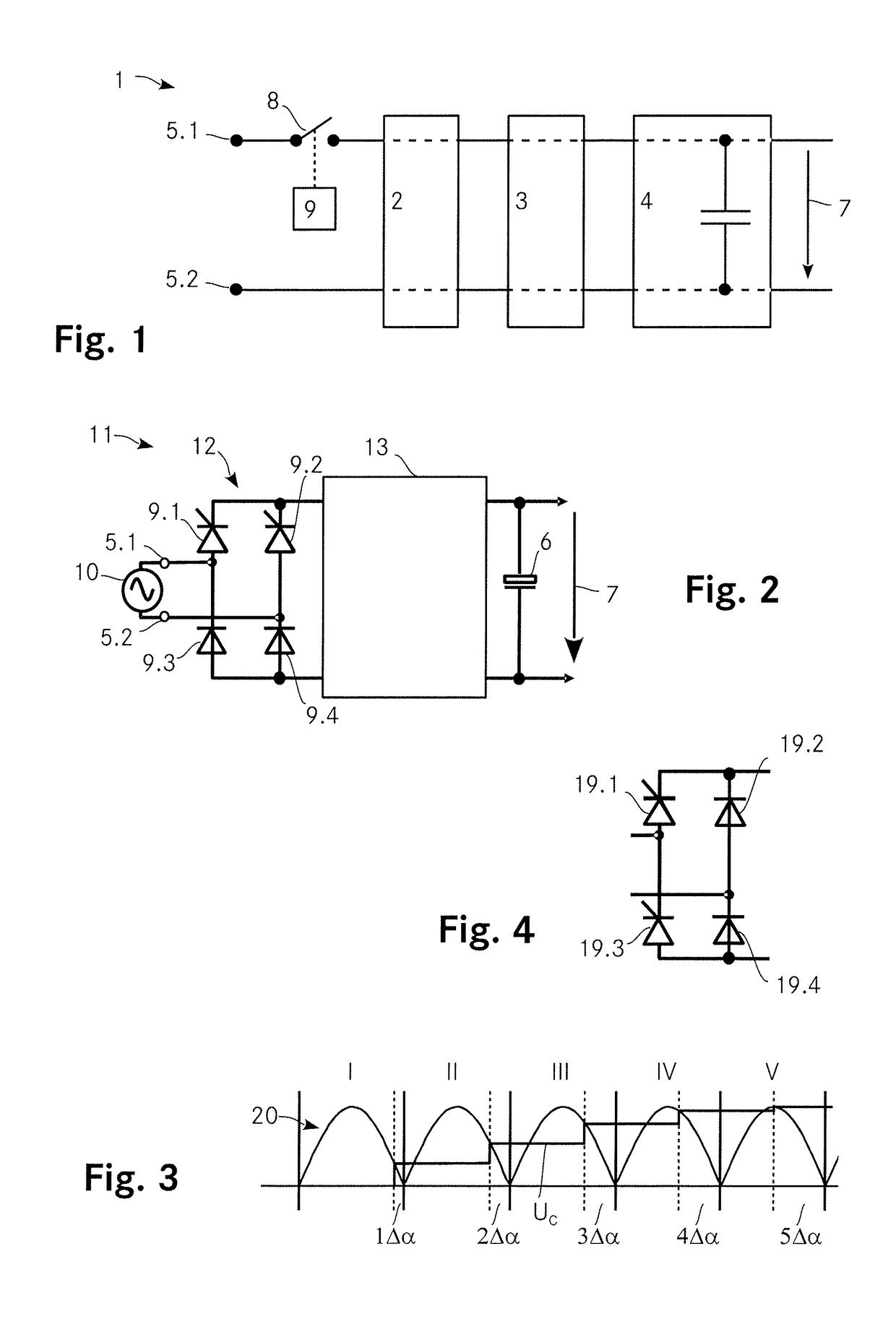
[0059]FIG. 1 shows a schematic depiction of a converter arrangement 1 according to the invention. The converter arrangement 1 includes two input terminals 5.1, 5.2 for connecting an AC input voltage, an input stage 2, a converter stage 3 and an output stage 4 that includes an output capacitor 6. A DC output voltage 7 is provided across the output capacitor 6.

[0060]The converter arrangement 1 further includes a controllable switch 8 that is controlled by a control unit 9. By properly controlling the controllable switch 8 during startup, i. e. by switching it ON during each half period for a certain amount of time, the charge current flowing through the output capacitor 6 can be controlled to be rather small such that the inrush current is limited to a level that does not damage the converter arrangement 1.

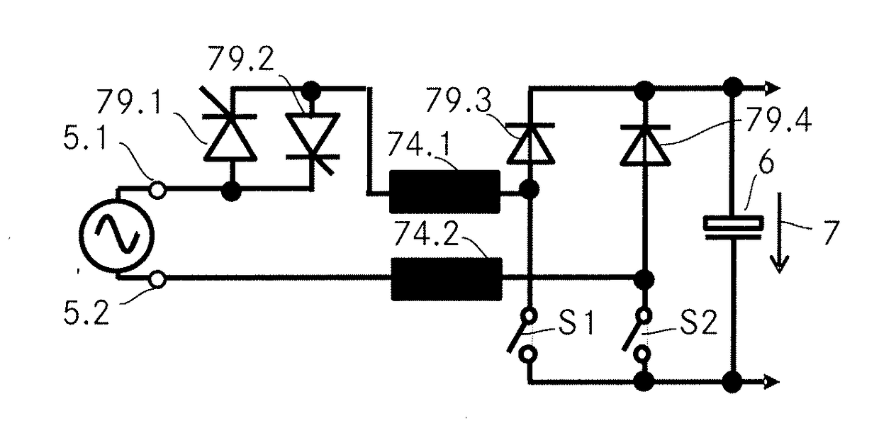
[0061]FIG. 2 shows another embodiment of the invention. The converter arrangement 11 includes a full-bridge rectifierl2 connected to the input terminals 5.1, 5.2 where a voltage sou...


PUM


Abstract

A boost PFC converter includes a rectifier, a converter and an output stage comprising an output capacitor where the DC output voltage is provided across the output capacitor. The rectifier includes four rectifying elements connected in a full bridge configuration where the upper two of these four rectifying elements are thyristors and where the lower two are diodes. In that the thyristors are controlled such as to be open for only a part of each half period of the input voltage, the amount of current per half period that is passed to the output capacitor is controllable and can be made very small. Accordingly, the charge current for precharging the output capacitor can be controllably limited such that a bulky precharge resistor is not required anymore to avoid high inrush currents.

Description

[0001]This application is a Continuation of copending application Ser. No. 14 / 535,926, filed on Nov. 7, 2014, which claims priority under 35 U.S.C. § 119(a) to Application No. 13192249.4 filed in Europe on Nov. 8, 2013, all of which are hereby expressly incorporated by reference into the present application.TECHNICAL FIELD[0002]The invention relates to converter arrangements including an input stage comprising two input terminals for connecting an AC input voltage, a converter stage for converting the AC input voltage to a DC output voltage and an output stage comprising an output capacitance, where the DC output voltage is provided across the output capacitance, the converter arrangement further including a controllable switch arranged in a current path from one of the two input terminals to the other and including said output capacitance and a control unit adapted to control the controllable switch for precharging the output capacitance at a startup of the converter arrangement. T...

Claims


Application Information

Patent Timeline
Patent Type & Authority Applications(United States)
IPC IPC(8): H02M1/42H02M7/12H02M1/32H02M1/36
CPCY02B70/126H02M7/125H02M1/4233H02M1/42H02M1/36H02M1/32H02M7/12H02M1/4225H02M1/0085Y02B70/10H02M1/081H02M7/145
Inventor HUFNAGEL, MICHAELSCHAFMEISTER, FRANK
Owner DELTA ELECTRONICS (THAILAND) PUBLIC CO LTD
Why Eureka
Try Eureka