
Systems and Methods for Routing a Vessel Line Such as a Catheter Within a Vessel

a technology of system and method, which is applied in the direction of instrumentation, diagnostic recording/measuring, reconstruction from projection, etc., can solve the problems of significant time delay, damage to surrounding tissue, and significant impact on patient outcome, so as to reduce the variance of time to complete particular steps, reduce the time to reperfusion, and reduce the effect of time on a wider scal

Active Publication Date: 2018-03-29
MENTICE
View PDF6 Cites 14 Cited by
  • Summary
  • Abstract
  • Description
  • Claims
  • Application Information

AI Technical Summary

Benefits of technology

The invention describes a system and method for improving the efficiency of surgical procedures using catheter systems. The method includes creating a 3D model of the patient's vasculature based on specific image data, marking the destination within the model, determining the best route from the entry point to the destination based on parameters like access point and physical properties of catheter systems, and ranking the catheter systems based on their suitability for navigating the route. This helps to select the most suitable system for the surgical procedure. The system includes an imaging scanner and a computer program that facilitate the process of creating the 3D model and analyzing it to determine the best route and ranking of catheter systems. Overall, this improves the efficiency of surgical procedures by optimizing the selection of catheter systems and streamlining the procedure.

Problems solved by technology

If the catheter is too stiff, it may cause damage to the surrounding tissue as it navigates around corners of the vessels, if it is able to be moved at all and / or may cause significant time delays in completing the medical procedure.
In certain procedures, such as endovascular interventions to remove a blood clot from the brain of a patient who has had an ischemic stroke, “time is brain”, meaning that delays in completing a procedure can significantly affect the outcome for the patient.
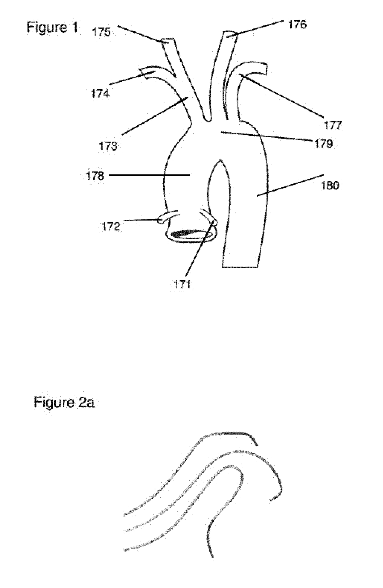
In this situation the angle between the descending aorta and the left common carotid artery is more acute making the catheterization more challenging.
In addition, older people often have increasing tortuosity and / or stiffness of their vessels and also the vessels may become longer.
A catheter system which is too stiff can straighten out tortuous vessels (which may or may not be advantageous) and / or produce damage to the vessel as it is being navigated through a tight curve.
However, if the catheter is too flexible, it may not be able to maintain its position within the vessel and, for example, fall back into the aortic arch after it has been successfully guided into the left internal carotid artery (especially as further catheters and tools are being advanced through the catheter to enter the brain vessels and / or as the guide wire is withdrawn).
In some cases additional catheters face friction as they are being advanced and as such, this creates a backward force on the guiding catheter hence preventing the interventionist from completing a procedure and / or wasting time in removing a catheter and selecting and navigating a different catheter into position.
However, a guide catheter that is too flexible may present problems during the procedure if it is unable to properly support microcatheters, microwires and other equipment within it for subsequent steps of the procedure.
Importantly, throughout the process various complexities can occur where the DC does not go into the vessel of interest but ends up somewhere else.
However in the case of many emergencies, particularly those that are as emergent and complicated as acute stroke, there are limitations in terms of how much opportunity a trainee gets.
As a result, while medical trainees may be exposed to complicated procedures, the amount of hands on experience they acquire during these emergencies may take many years to acquire.
While effective, current simulators are limited in that while they simulate “real” patient anatomies, derived from real imaging data, they do not represent the anatomies of an actual patient who is in immediate need of a procedure.
That is, while current simulation systems allow physicians to practice on simulated patients, they are not actual patients whose specific anatomies are before them.
Moreover, while a physician may be able to practice on various simulated patients with known variations and complexities in their anatomy, such practice may have become dated by the time an actual patient presents having a particular anatomy.

Method used


Image

  • Systems and Methods for Routing a Vessel Line Such as a Catheter Within a Vessel
  • Systems and Methods for Routing a Vessel Line Such as a Catheter Within a Vessel
  • Systems and Methods for Routing a Vessel Line Such as a Catheter Within a Vessel

Examples


Embodiment Construction

Introduction

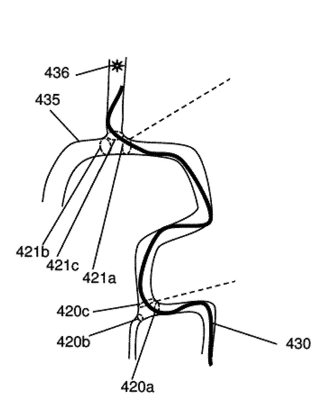
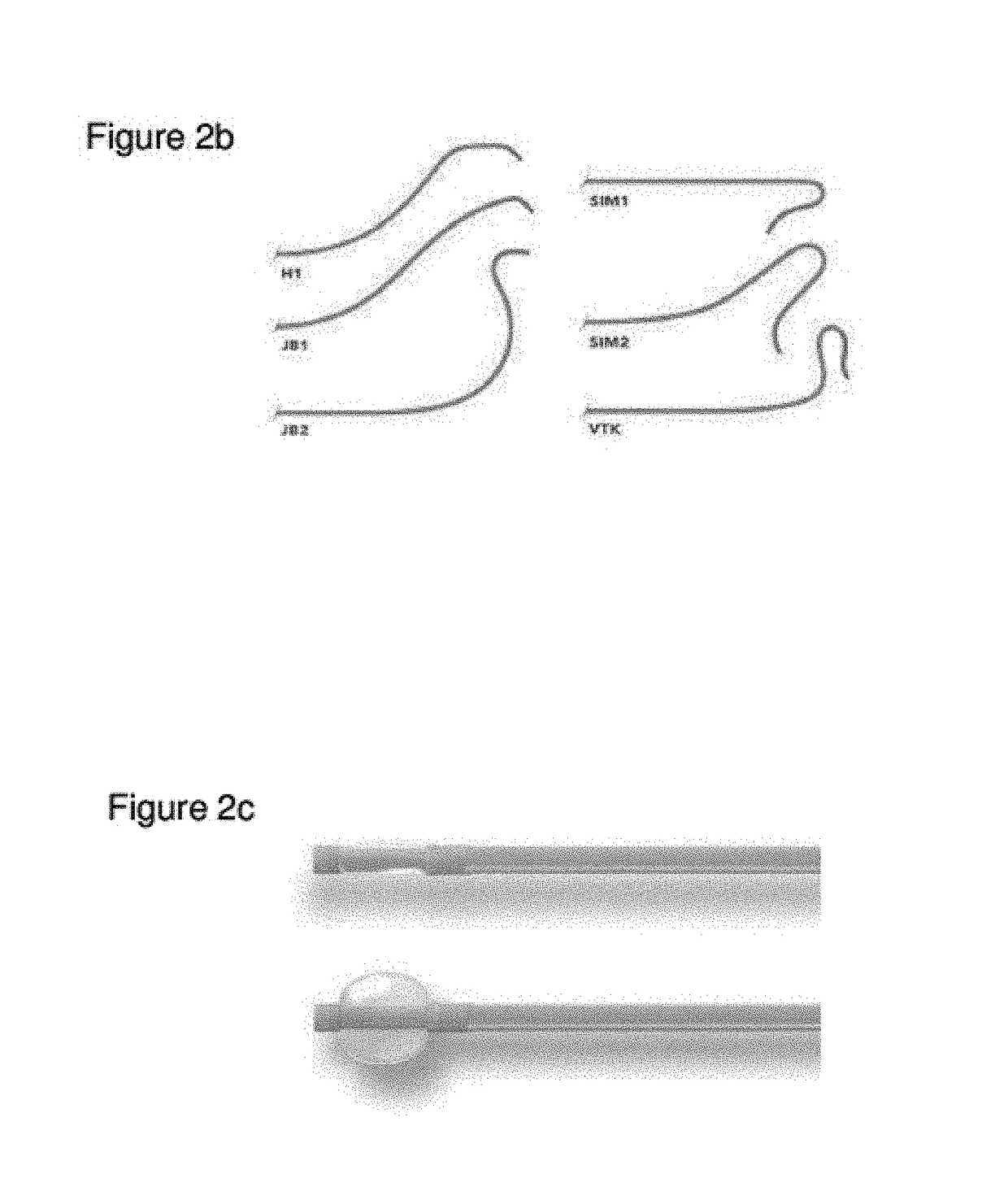
[0147]With reference to the figures there is described an apparatus configured to determine the route of a vessel line within a vessel in order to determine which (if any) vessel line can or should be used for a particular task.

[0148]All terms have definitions that are reasonably inferable from the drawings and description.

[0149]Various aspects of the invention will now be described with reference to the figures. For the purposes of illustration, components depicted in the figures are not necessarily drawn to scale. Instead, emphasis is placed on highlighting the various contributions of the components to the functionality of various aspects of the invention. A number of possible alternative features are introduced during the course of this description. It is to be understood that, according to the knowledge and judgment of persons skilled in the art, such alternative features may be substituted in various combinations to arrive at different embodiments of the present in...


PUM


Abstract

The invention relates to systems and methods enabling a personalized solution for allowing more efficient access to the carotid artery (or vertebral arteries) in patients needing endovascular / neurointervention procedures using catheter systems.

Description

FIELD OF THE INVENTION[0001]The invention relates to systems and methods enabling a personalized solution for allowing more efficient access to the carotid artery (or vertebral arteries) in patients needing endovascular / neurointervention procedures.BACKGROUND OF THE INVENTION[0002]As is known, the human or animal body has an extensive network of blood vessels including both the venous and arterial systems for circulating blood throughout the body as a whole as well as the organs of the body.[0003]In recent years, a variety of traumatic surgical procedures have been replaced with procedures that involve the use of one or more catheters being advanced through the vascular system of the body to gain access to diagnose and / or treat issues involving the vasculature of a particular organ. For example, strokes (e.g. ischemic strokes caused by blood clot blockages in the brain); coronary artery blockages within the heart; and various heart defects may be treated by advancing catheters to th...

Claims


Application Information

Patent Timeline
IPC IPC(8): A61B34/10A61B34/20G06T11/00G06T17/10
CPCA61B34/10A61B34/20G06T11/003G06T17/10A61B2034/107A61B2034/2065G06T2200/08A61B5/103A61B34/00
Inventor GOYAL, MAYANK
Owner MENTICE
Learn More