
Fitting with a collar for a power transmission system

a power transmission system and collar technology, applied in the direction of supporting insulators, electric devices, insulators, etc., can solve the problems of limiting the effectiveness of the corona ring, posing serious electromagnetic interference to the system and its vicinity, and allowing an inexperienced technician to install the corona ring upside-down or in another improper orientation

Active Publication Date: 2018-03-29
MACLEAN POWER LLC
View PDF22 Cites 5 Cited by
  • Summary
  • Abstract
  • Description
  • Claims
  • Application Information

AI Technical Summary

Benefits of technology

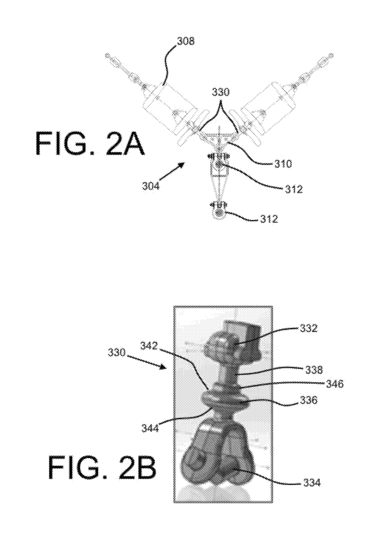
The present invention provides a fitting for a power transmission system that includes a collar with an oblate spheroid that can securely attach to a corona ring assembly. The collar has a notch with a diameter greater than the outer diameter of the neck and has a receiving channel for a grip element to tighten around the collar. The fitting also has a socket eye to receive an insulator and a Y-clevis to attach to a yoke plate. The system also includes a second fitting and a yoke plate in a V configuration to provide flexibility in the power transmission. The technical effects of this invention include improved system reliability, resistance to environmental factors, and increased flexibility for power distribution.

Problems solved by technology

If not controlled, it poses serious electromagnetic interference to the system and its vicinity.
One disadvantage of currently-known hardware coupling or otherwise securing the insulator to a corona ring is the ability of the corona ring to be installed upside-down or in another improper orientation by an inexperienced technician.
The improper installation of a corona ring may limit its effectiveness and cause the insulator to become electrically overstressed and / or cause the insulative materials to deteriorate over time.

Method used


Image

  • Fitting with a collar for a power transmission system
  • Fitting with a collar for a power transmission system
  • Fitting with a collar for a power transmission system

Examples


Embodiment Construction

[0021]The present embodiments may be better understood with reference to the following drawings and description. The components in the figures are not necessarily to scale, emphasis instead being placed upon illustrating certain principles.

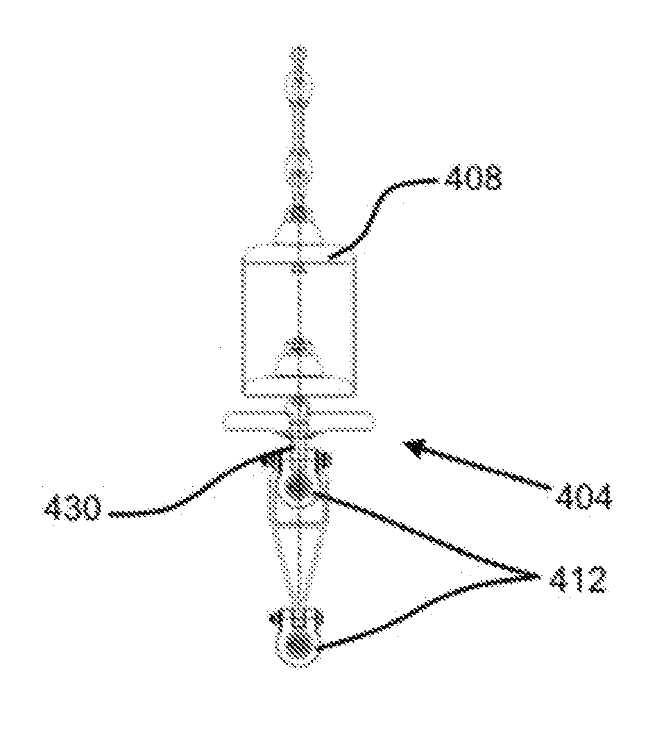
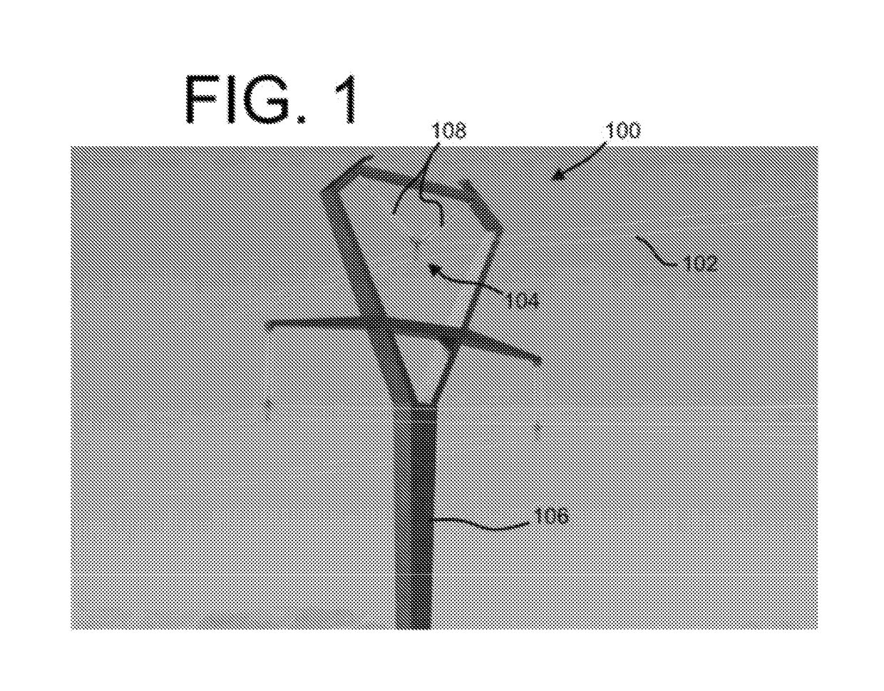
[0022]FIG. 1 shows a perspective view of a power transmission system 100 with several power lines 102. A support system 104 may couple the transmission power lines 102 to a transmission tower 106 (which may include a pole, a lattice tower, etc.). An insulator 108 (which may refer to an assembly of a plurality of insulative plates and other components associated with a suspension line) may be located between the support system 104 and the transmission tower 106 to provide suitable electrical insulation between the electrically-charged conductors of the transmission power lines 102 and the transmission tower 106. As shown, the insulator 108 may form and / or may be attached to a suspension line that may suspend the support system 104 and the transmiss...


PUM


Abstract

The present disclosure provides a fitting for a power transmission system. The fitting may include a first end configured to couple to an end of an insulator, a second end configured to couple to a power line, a collar located between the first end and the second end, and a neck located between the collar and the first end. An outer diameter of the collar may be greater than an outer diameter of the neck. A power transmission system with a fitting and corona ring assembly is also provided.

Description

CROSS-REFERENCE TO RELATED APPLICATIONS[0001]This application claims priority to U.S. Provisional Patent Application Ser. No. 62 / 398,918, entitled “FITTING WITH A COLLAR FOR A POWER TRANSMISSION SYSTEM,” and filed Sep. 23, 2016, which is incorporated by reference herein in its entirety.BACKGROUND[0002]In high-voltage transmission power lines, corona and radio interference are typical phenomena acting on the power line hardware. Corona, which is an electrical discharge brought on by the ionization of a fluid (e.g., air) surrounding an electrically-charged conductor, generally occurs when the electric field around a conductor is high enough to form a conductive region, but not high enough to cause electrical breakdown or arcing to nearby objects. Radio interference (also called electromagnetic interference) is the conduction or radiation of a radio frequency energy that may disrupt or interfere with electromagnetic waves of the same wavelength. If not controlled, it poses serious elec...

Claims


Application Information

Patent Timeline
IPC IPC(8): H01B17/16H01B17/44
CPCH01B17/16H01B17/44H01B17/04
Inventor LIN, WEI-CHUNGSCOGIN, BRYAN
Owner MACLEAN POWER LLC
Learn More