Combined oil control ring

a technology of oil control ring and oil control ring, which is applied in the direction of piston rings, machines/engines, mechanical equipment, etc., can solve the problems of lubricating oil, failure to exhibit a sufficient oil control function, and troublesome engine functions, so as to prevent the retention of oil and expand the space

Active Publication Date: 2018-04-05
RIKEN CO LTD
View PDF32 Cites 1 Cited by
  • Summary
  • Abstract
  • Description
  • Claims
  • Application Information

AI Technical Summary

Benefits of technology

[0023]The oil ring of the present invention comprises grooves extending in a substantially circumferential direction and recessed when viewed along a radial direction, in intermediate portions of a spacer expander, such that the grooves provide substantially expanded space between the intermediate portions and the side rails. With an oil flow generated in the intermediate portions in a circumferential direction, oil can be flown to lower portions of a spacer expander having much larger space than that of penetrating holes of tabs disclosed as oil-flowing holes in Patent References 7 and 8, thereby preventing the retention of oil. With each groove having a raised bottom when viewed along a substantially circumferential direction, oil easily flows from the intermediate portions to both circumferential sides. When combined with a resin coating or a metal coating such as Ni for preventing sticking, excellent effect of preventing the retention of oil can be further exhibited. As a result, the accumulation of oil sludge can be prevented even in a small-width, low-tension oil ring. With this structure, the oil ring can exhibit sufficient durability in an operation pattern repeating the start and stop of an engine, without residing oil in space between the spacer expander and the side rails even when the engine is stopped.

Problems solved by technology

In automobile engines, lubricating oil is exposed to a blowby gas and heated for a long period of operation, so that the lubricating oil is contaminated with unburned hydrocarbons and degenerated oil additives (called “oil sludge” as a whole).
The oil sludge attached to and accumulated on engine parts likely wears the parts and clogs lubricating oil paths, causing troubles in the functions of engine parts such as combined oil control rings (called “oil rings” unless otherwise mentioned).
In the oil rings, spacer expanders and side rails are stuck to each other in the worst case, hindering the movement of separate side rails, and thus failing to exhibit a sufficient oil-controlling function.
When sticking occurs, the followability of the side rails to the cylinder wall decreases extremely, resulting in drastically increased oil consumption.
However, the coating methods of Patent References 1-5 suffer excess steps leading to cost increase, and the hole-forming method of Patent Reference 6 needs difficult working, making the oil rings expensive.
As a result, sufficient durability is not obtained in such an operation pattern as undergoing repeated start and stop of engines.

Method used


Image

  • Combined oil control ring
  • Combined oil control ring
  • Combined oil control ring

Examples


example 1

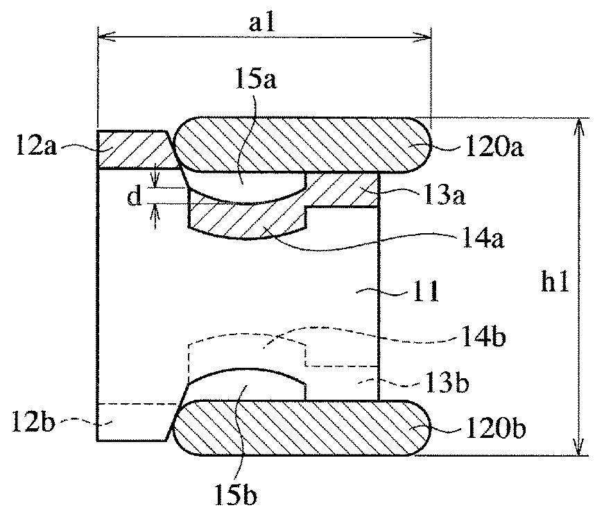
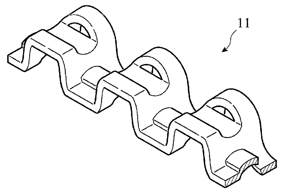
[0036]A SUS440 wire of 0.35 mm×1.72 mm was formed into side rails, and a SUS304 wire of 0.25 mm×1.9 mm was formed into a spacer expander, to produce a combined oil ring having a nominal diameter d1 of 71 mm, a nominal combined width h1 of 2.0 mm, and a combined thickness a1 of 2.3 mm. The spacer expander had a pitch of 2.7 mm from an upper portion (lower portion) to an upper portion (lower portion), and each groove in the intermediate portion had a curved surface shape with a depth d of 0.1 mm as shown in FIGS. 1(a) and 1(b). There were spaces 15a, 15b of 0.2 mm between the deepest points of grooves in the intermediate portions of the spacer expander and the side rails.

example 2

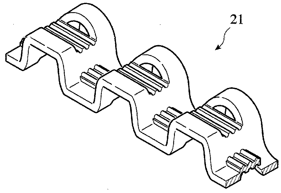
[0037]As shown in FIGS. 3(a) and 3(b), a combined oil ring was produced in the same manner as in Example 1, except for changing each groove in the intermediate portion of the spacer expander to a groove constituted by four flat planes such that it was raised in a reverse V shape when viewed along a circumferential direction. The depth d′ of each groove at a top of the raised bottom was 0.1 mm. Spaces 15a, 15b between the deepest points of the intermediate portions of the spacer expander and the side rails were as wide as 0.2 mm.

example 3

[0039]A SUS304 wire for a spacer expander used in Example 1 was provided with a Ni plating comprising a half-luster Ni plating layer and a bright Ni plating layer using a sulfamate solution, and subjected to a softening heat treatment at 600° C. for 30 seconds. The resultant Ni plating had a thickness of 5 μm and hardness of 214 HV0.01. A combined oil ring was produced in the same manner as in Example 1 except for using this Ni-plated wire.


PUM


Abstract

To provide a combined oil control ring comprising a pair of upper and lower side rails and an axially corrugated spacer expander having upper and lower portions for automobile engines, which is capable of keeping an excellent oil-controlling function without sticking between a spacer expander and side rails even in a long period of engine operation, the upper and lower portions of the spacer expander have tabs pushing inner peripheral surfaces of the side rails, projections supporting the side rails, and intermediate portions between the tabs and the projections; each intermediate portion opposing the side rail has at least one groove extending in a substantially circumferential direction is recessed when viewed along a radial direction.

Description

FIELD OF THE INVENTION[0001]The present invention relates to a combined oil control ring mounted to a piston for an internal combustion engine, particularly to a combined oil control ring comprising a pair of upper and lower side rails and an axially corrugated spacer expander having upper and lower portions.BACKGROUND OF THE INVENTION[0002]In automobile engines, lubricating oil is exposed to a blowby gas and heated for a long period of operation, so that the lubricating oil is contaminated with unburned hydrocarbons and degenerated oil additives (called “oil sludge” as a whole). The oil sludge includes oil sludge precursors having relatively low viscosity. The oil sludge attached to and accumulated on engine parts likely wears the parts and clogs lubricating oil paths, causing troubles in the functions of engine parts such as combined oil control rings (called “oil rings” unless otherwise mentioned). In the oil rings, spacer expanders and side rails are stuck to each other in the w...

Claims


Application Information

Patent Timeline
Patent Type & Authority Applications(United States)
IPC IPC(8): F16J9/06
CPCF16J9/068F02F5/00F16J9/20F16J9/12
Inventor SHIMIZU, HIROSHIYABUNE, HIROYUKI
Owner RIKEN CO LTD
Why Eureka
Try Eureka