
Liquid crystal lens and 3D display device

Active Publication Date: 2018-04-12
WUHAN CHINA STAR OPTOELECTRONICS TECH CO LTD
View PDF0 Cites 5 Cited by
  • Summary
  • Abstract
  • Description
  • Claims
  • Application Information

AI Technical Summary

Benefits of technology

The present invention provides a liquid crystal lens that can decrease thickness, reduce o light leakage, and achieve high quality 3D image display. This is achieved by utilizing a metal wire grid to function both as an electrode and a polarizer. Additionally, the invention eliminates the need for an additional polarizer adhesion, which further reduces thickness. The invention also includes a 3D display device that can achieve the same benefits. Overall, this innovation leads to a thinner and better 3D display technology.

Problems solved by technology

Such method leads to the decreased 3D image resolution of the display panel in comparison with 2D panels.
The 3D effect is totally far from perfection, suffering low image resolutions.
Moreover, the adding 3D modules pose negative effect on the 2D display effect as well, which is totally unacceptable.
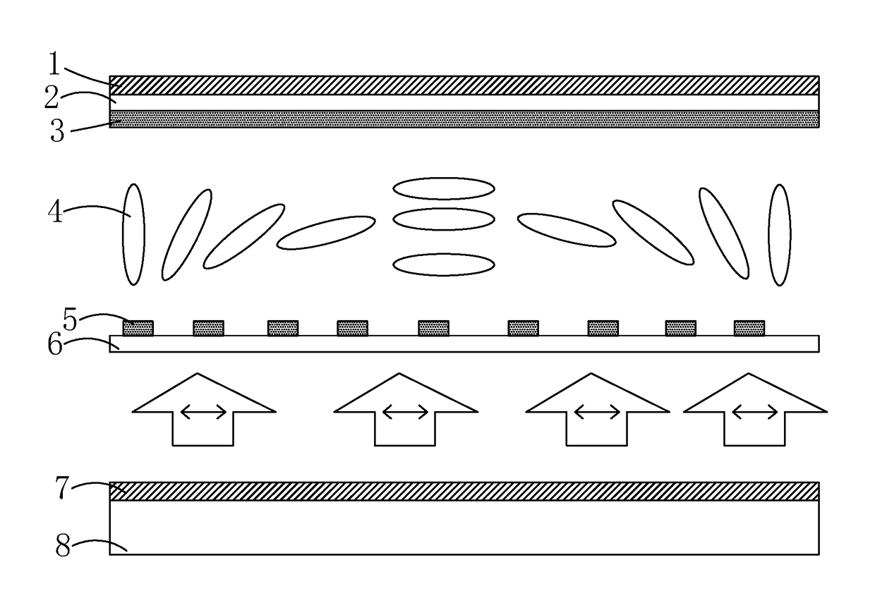
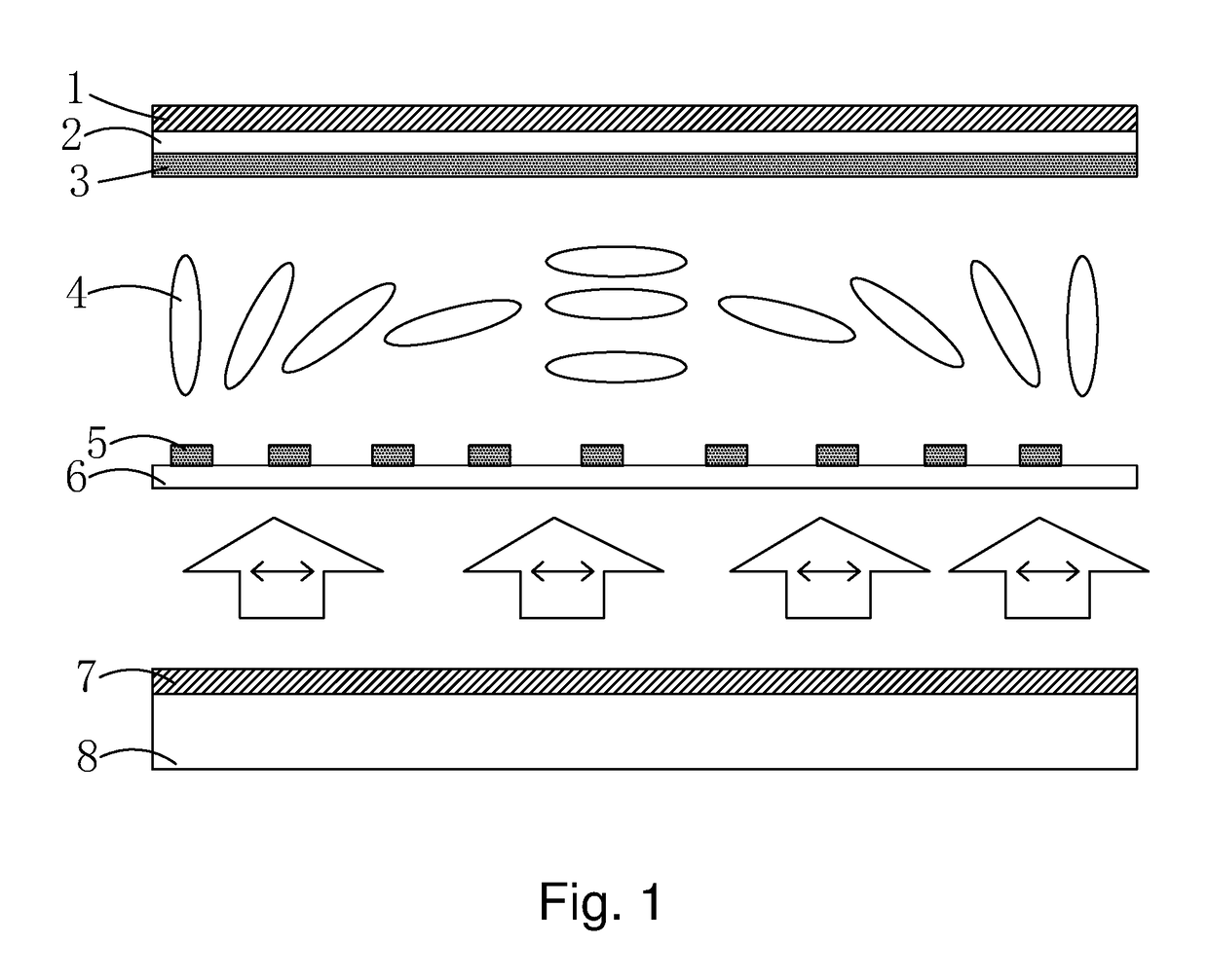
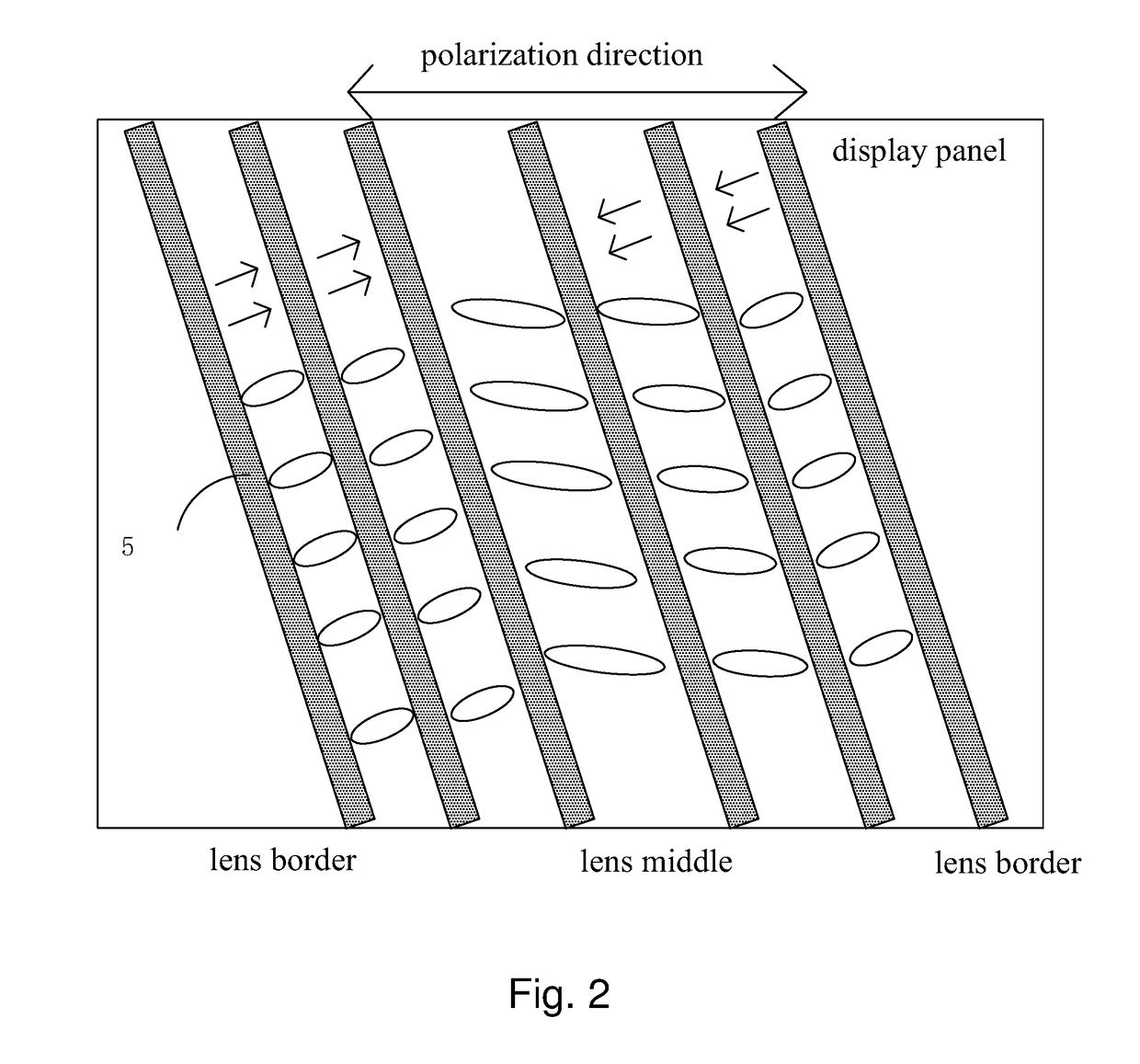
However, for reducing the influence of the Moire pattern to the display result, as shown in FIG. 2, the alignment of the liquid crystal lens relative to the display pixels is generally arranged to be tilted; and because the bias voltages of the various strip lens electrodes 5 are different, the transverse electrical field component can be easily formed among the strip lens electrodes 5, and the direction of the transverse component and the theoretical twist direction are not consistent, which results in that the liquid crystal molecules will deviate from the original alignment direction.
Due to the larger voltage variation at the border of the liquid crystal lens, such issue becomes more serious.
The o light in the liquid crystal lens does not have the lens effect, and thus to have the 2D interference signal to reduce the 3D display result.

Method used


Image

  • Liquid crystal lens and 3D display device
  • Liquid crystal lens and 3D display device
  • Liquid crystal lens and 3D display device

Examples


Embodiment Construction

[0040]For better explaining the technical solution and the effect of the present invention, the present invention will be further described in detail with the accompanying drawings and the specific embodiments.

[0041]Please refer to FIG. 3. The present invention first provides a liquid crystal lens, comprising: an upper glass substrate 10, a lower glass substrate 50, which is oppositely located to the upper glass substrate 10, a metal wire grid 20 located on one side of the upper glass substrate 10 close to the lower glass substrate 50, a plurality of strip electrodes 40 which are in parallel spaced arrangement on one side of the lower glass substrate 50 close to the upper glass substrate 10, and a liquid crystal layer 30 located between the lower glass substrate 50 and the upper glass substrate 10.

[0042]Specifically, the metal wire grid 20 comprises a plurality of metal wires 21 which are in parallel spaced arrangement, and a dielectric layer 22 located under the plurality of metal ...


PUM


Abstract

The present invention provides a liquid crystal lens and a 3D display device. By utilizing the metal wire grid (20) to realize the functions of electrode and polarizer at the same time, and the polarizer filters the o light to solve the display degradation issue due to the o light leakage, and corresponding high quality 3D image display is realized. By combining function of the polarizer and the electrode in the metal wire grid (20), the additional polarizer adhesion is no longer required, which can effectively decrease the thickness of the liquid crystal lens. The present invention further provides a 3D display device, which can decrease the thickness of the 3D display device to realize the high quality 3D image display.

Description

FIELD OF THE INVENTION[0001]The present invention relates to a display technology field, and more particularly to a liquid crystal lens and a 3D display device.BACKGROUND OF THE INVENTION[0002]While the digital audio and video technology enters the high resolution time, the Three Dimension (3D) stereoscopic display technology has been drawn the attention and favor of the people data by day. The naked eye 3D technology gets rid of the complicated accessory equipments and goes over big. There are kinds of technologies to realize the naked eye 3D display, such as optical grating, liquid crystal lens, most of which at present is mainly based on special division of subpixels. Such method leads to the decreased 3D image resolution of the display panel in comparison with 2D panels. The 3D effect is totally far from perfection, suffering low image resolutions. Moreover, the adding 3D modules pose negative effect on the 2D display effect as well, which is totally unacceptable.[0003]The princ...

Claims


Application Information

Patent Timeline
IPC IPC(8): G02F1/1335G02B27/26G02F1/29G02B30/25
CPCG02F1/133528G02F1/133526G02B27/26G02F1/29G02F2001/133548G02F1/134309G02B30/25G02B30/27G02F1/133548G02B5/3058G02F1/291
Inventor ZHA, GUOWEI
Owner WUHAN CHINA STAR OPTOELECTRONICS TECH CO LTD
Learn More