Quantum dot backlight module

a backlight module and quantum dot technology, applied in the field of can solve the problems of low and achieve the effect of improving brightness and reducing the brightness of conventional quantum dot backlight modules

Inactive Publication Date: 2018-04-19
WUHAN CHINA STAR OPTOELECTRONICS TECH CO LTD
View PDF2 Cites 1 Cited by
  • Summary
  • Abstract
  • Description
  • Claims
  • Application Information

AI Technical Summary

Benefits of technology

[0022]The efficacy of the present invention is that the present invention provides a quantum dot backlight module, which comprises a quantum dot film arranged on a side of the light guide plate that is distant from the light reflector board and an optical coating layer arranged on a side of the quantum dot film that is distant from the light guide plate, or alternatively comprises a quantum dot tube arranged between a light guide plate and a backlight source and an optical coating layer arranged on a side of the light guide plate that is adjacent to the quantum dot tube, so that for the purpose of emission of white backlighting, the optical coating layer is used to reflect a part of monochromatic light emitting from the backlight source toward the quantum dot film or the quantum dot tube for re-excitation for light emission so as to increase excitation performance of the quantum dot film or the quantum dot tube, improve brightness and gamut of the quantum dot backlight module, and enhance product quality.

Problems solved by technology

However, the conventional quantum dot backlight modules all suffer a disadvantage of low brightness.

Method used


Image

  • Quantum dot backlight module
  • Quantum dot backlight module
  • Quantum dot backlight module

Examples


first embodiment

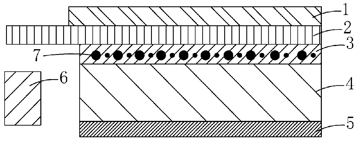
[0030]Referring to FIG. 3, a schematic view is provided for illustrating the structure of a quantum dot backlight module according to the present invention, which comprises: a light guide plate 10, a light reflector board 20 arranged on a surface of the light guide plate 10, a backlight source 30 arranged on a side of the light guide plate 10, and a quantum dot film 40 arranged on an opposite surface of the light guide plate 10.

[0031]The quantum dot film 40 has a surface that is distant from the light guide plate 10 and is provided with an optical coating layer 11. The optical coating layer 11 reflects light emitting from the backlight source 30 to excite the quantum dot film 40.

[0032]Specifically, the quantum dot film 40 comprises a quantum dot material 41 that can be excited to emit a color light having a color different from monochromatic light emitting from and the backlight source 30.

[0033]Specifically, in the instant embodiment, the backlight source 30 comprises a blue-light L...

second embodiment

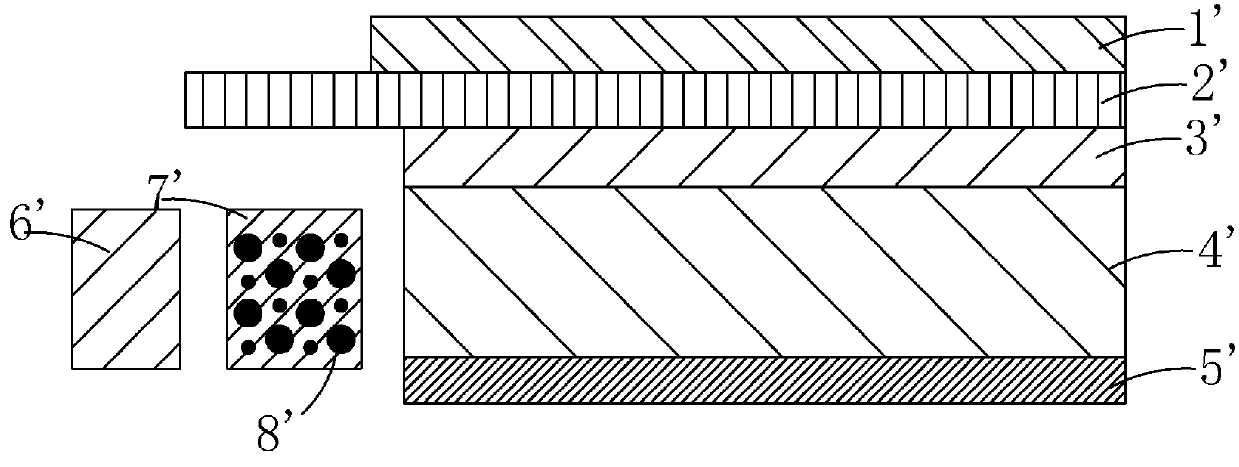
[0041]Referring to FIG. 4, a schematic view is provided for illustrating the structure of a quantum dot backlight module according to the present invention, which comprises: a light guide plate 10′, a light reflector board 20′ arranged on a surface of the light guide plate 10′, a quantum dot tube 30′ arranged at a side of the light guide plate 10′, and a backlight source 40′ arranged on one side of the quantum dot tube 30′ that is distant from the light guide plate 10′.

[0042]The light guide plate 10′ has a surface that is adjacent to the quantum dot tube30′ and is provided with an optical coating layer 11′. The optical coating layer 11′ reflects light emitting from the backlight source 40′ to excite the quantum dot tube 30′.

[0043]Specifically, the quantum dot backlight module further comprises a diffuser film 50′ arranged on a side of the light guide plate 10′ that is distant from the light reflector board 20′.

[0044]Specifically, the quantum dot tube 30′ comprises a quantum dot mate...


PUM


Abstract

The present invention provides a quantum dot backlight module, which includes a quantum dot film arranged on a side of the light guide plate that is distant from the light reflector board and an optical coating layer arranged on a side of the quantum dot film that is distant from the light guide plate, or alternatively includes a quantum dot tube arranged between a light guide plate and a backlight source and an optical coating layer arranged on a side of the light guide plate that is adjacent to the quantum dot tube, so that for the purpose of emission of white backlighting, the optical coating layer is used to reflect a part of monochromatic light emitting from the backlight source toward the quantum dot film or the quantum dot tube for re-excitation for light emission so as to increase excitation performance of the quantum dot film or the quantum dot tube, improve brightness and gamut of the quantum dot backlight module, and enhance product quality.

Description

BACKGROUND OF THE INVENTION1. Field of the Invention[0001]The present invention relates to the field of liquid crystal display technology, and in particular to a quantum dot backlight module.2. The Related Arts[0002]Thin film transistor-liquid crystal displays (TFT-LCDs) have a variety of advantages, such as thin device body, low power consumption, and being free of radiation, and thus have wide applications, such as liquid crystal televisions, mobile phones, personal digital assistants (PDAs), digital cameras, computer monitors, and notebook computer screens, so as to take a leading position in the field of flat panel displays. Most of the liquid crystal displays that are currently available in the market are backlighting liquid crystal displays, which comprise a liquid crystal panel and a backlight module. The working principle of the liquid crystal panel is that a drive voltage is applied to a thin-film transistor (TFT) array substrate and a color filter (CF) substrate to control...

Claims


Application Information

Patent Timeline
Patent Type & Authority Applications(United States)
IPC IPC(8): F21V8/00
CPCG02B6/005G02B6/0055G02B6/0073G02B6/0031G02B6/0026G02F1/133621G02F2001/133614G02F2202/36G02F1/133609G02F1/133615G02F1/133614H01L33/50
Inventor HAN, MEICHENG, YAN
Owner WUHAN CHINA STAR OPTOELECTRONICS TECH CO LTD
Why Eureka
Try Eureka