Shift register circuit, and display device including same

a shift register and register circuit technology, applied in the field of shift register circuits and display devices, can solve the problems of reducing the inability to appropriately scan the gate lines, and achieve the effect of improving the operation margin of the shift register circui

Inactive Publication Date: 2018-04-19
SHARP KK
View PDF4 Cites 4 Cited by
  • Summary
  • Abstract
  • Description
  • Claims
  • Application Information

AI Technical Summary

Benefits of technology

[0008]The configuration of the present invention allows each driving circuit of the shift register

Problems solved by technology

Further, in a case where the gate voltage of the output transistor and the discharge of the gate line are not enough when a gate line is put into the non-selected state, unintended

Method used


Image

  • Shift register circuit, and display device including same
  • Shift register circuit, and display device including same
  • Shift register circuit, and display device including same

Examples


embodiment 1

(Configuration of Liquid Crystal Display Device)

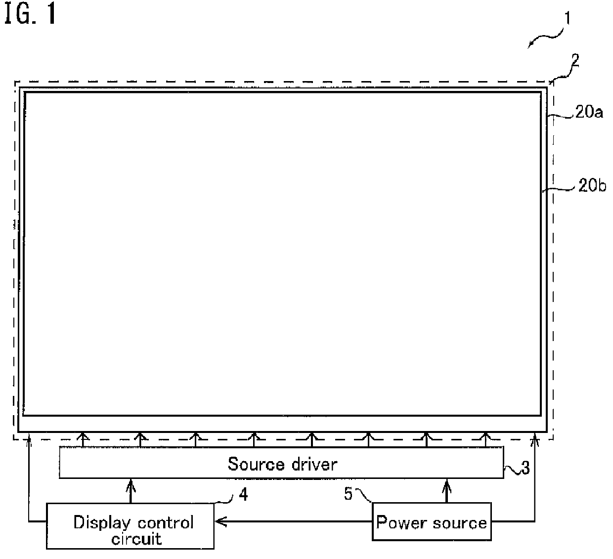
[0075]FIG. 1 is a schematic diagram illustrating a schematic configuration of a liquid crystal display device according to the present embodiment. The liquid crystal display device 1 includes a display panel 2, a source driver 3, a display control circuit 4, and a power source 5. The display panel 2 includes an active matrix substrate 20a, a counter substrate 20b, and a liquid crystal layer (not illustrated) interposed between these substrates. Though illustration is not shown in FIG. 1, a pair of polarizers sandwich the active-matrix substrate 20a and the counter substrate 20b A black matrix, and red (R), green (G), and blue (B) color filters, and a common electrode (all not illustrated) are formed on the counter substrate 20b.

[0076]As illustrated in FIG. 1, the active matrix substrate 20a is electrically connected with the source driver 3 formed in a flexible substrate. The display control circuit 4 is electrically connected with th...

embodiment 2

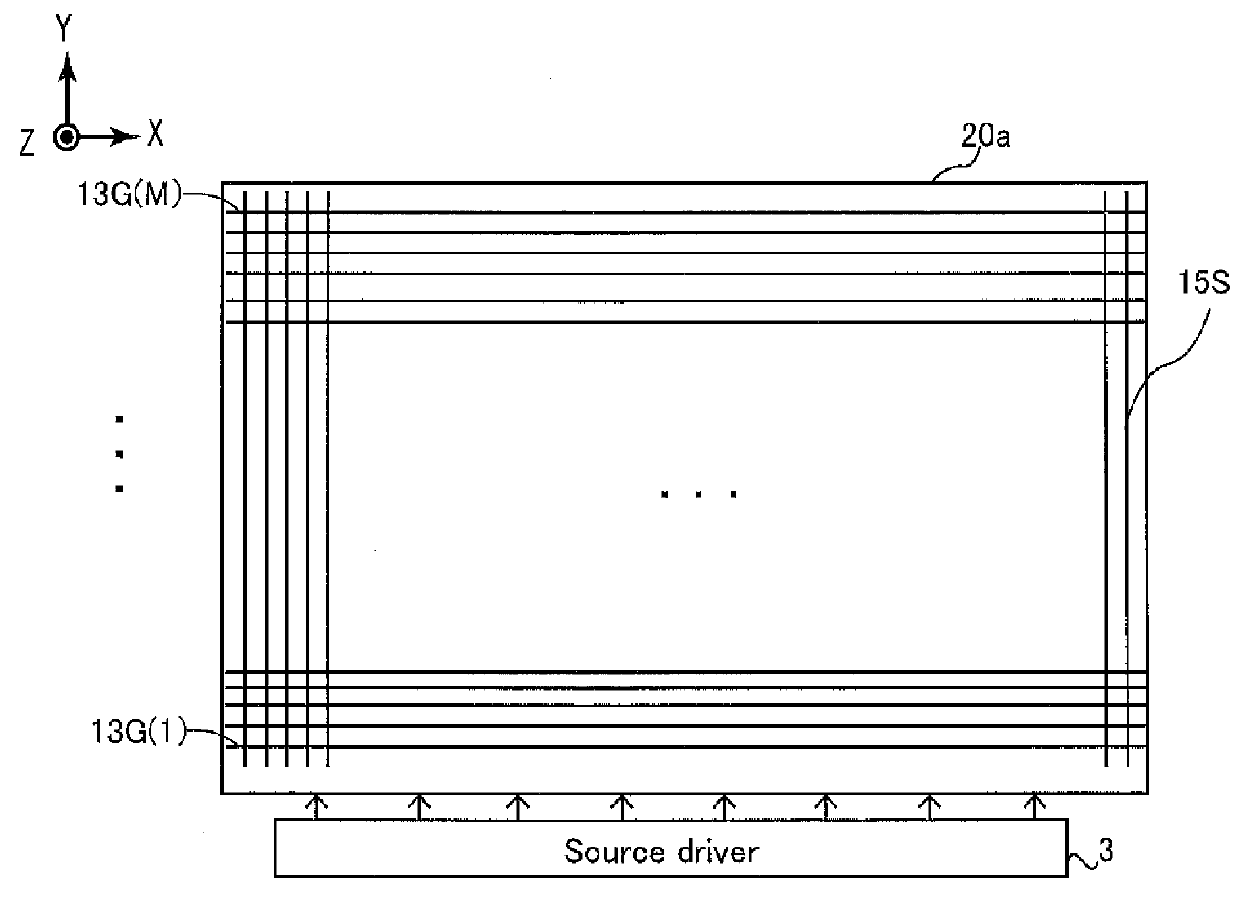
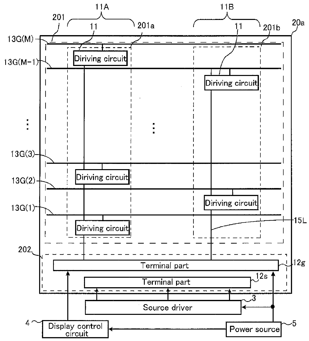
[0136]In the foregoing descriptions of Embodiment 1 and the application example of the same, examples are described in which a decrease in the precharge voltage of the netA is prevented so that the operation margin of the gate driver is improved. One of factors for the decrease in the operation margin of the gate driver is unsatisfactory pulldown of the potential of the netA when the gate line is switched into a non-selection state. Particularly, in a case where the gate driver is arranged in the display region, the potential of the netA cannot be pulled down surely to the L level in some cases, due to influences of parasitic capacitances generated between the gate driver and the elements provided in the display region such as the source lines 15S and the lines 15L. In the description of the present embodiment, an example is described in which, in order to improve the operation margin of the gate driver, the potential of the netA is more surely pulled down when the gate line is put ...

embodiment 3

[0149]In the foregoing description of Embodiment 2, an example is described in which, in order to improve the operation margin of the gate driver, to the gate terminal of the TFT-K that functions as a gate voltage discharge unit, a netA of another driving circuit is connected, so that the driving power of the TFT-K is improved. In the present embodiment, the discharge of a gate line upon a transition during the non-selection period while the gate line is not selected is enhanced, so that the operation margin of the gate driver is improved. Hereinafter, configurations different from those in Embodiment 2 are described.

(Circuit Configuration)

[0150]FIG. 16 illustrates an exemplary equivalent circuit of a driving circuit 112 in the present embodiment. As illustrated in FIG. 16, in the driving circuit 112(n) that drives the gate line 13G(n), regarding the TFT-K for pulling down the potential of the netA(n), the gate line 13G(n+2) is connected to the gate terminal thereof, the netA(n) is ...


PUM


Abstract

Each driving circuit in a shift register includes an output unit, a precharge unit, a boosting unit, a gate voltage discharge unit, a gate line discharge unit, and an internal line netA. The output unit includes a TFT(F) that outputs a selection voltage to a gate line. The precharge unit includes a TFT(B) that outputs a control voltage for causing the TFT in the output unit to operate. The boosting unit boosts up a gate voltage of the TFT in the output unit through a capacitor (Cbst). The gate voltage discharge unit includes a TFT(K) that pulls down this gate voltage during a non-selection period while the gate line is not selected. The gate line discharge unit includes a TFT(L) that outputs a non-selection voltage to the gate line during the non-selection period while the gate line is not selected. The internal line is connected to a gate terminal of the TFT in the output unit, the precharge unit, the gate voltage discharge unit, and the boosting unit. A gate terminal of at least one of the TFTs in the precharge unit, the gate voltage discharge unit, and the gate line discharge unit is connected to an internal line in another driving circuit.

Description

TECHNICAL FIELD[0001]The present invention relates to a shift register circuit, and a display device including the same.BACKGROUND ART[0002]A shift register circuit that sequentially scans a plurality of gate lines provided on an active matrix substrate has been known conventionally. The shift register circuit includes a driving circuit for every gate line, the driving circuit including an output transistor that switches the gate line into a selected state, a precharge transistor that precharges a gate voltage for the output transistor, and a bootstrap capacitor that boots up the precharge voltage. For the precharge transistor, a diode-connected transistor is used, and the precharge voltage has a voltage value that is decreased for the threshold voltage for the precharge transistor. If the precharge voltage decreases due to an increase of the threshold voltage caused when the transistor degrades, the gate voltage of the output transistor also decreases, which causes the operation of...

Claims


Application Information

Patent Timeline
IPC IPC(8): G09G3/36G11C19/28
CPCG09G3/3648G11C19/28G09G2310/0286G09G3/3677G09G2300/0408G09G2300/0426G09G2310/08
Inventor TANAKA, KOHHEINOMA, TAKESHINISHIYAMA, TAKAYUKIYONEBAYASHI, RYOOGAWA, YASUYUKIYAMAMOTO, KAORU
Owner SHARP KK
Why Eureka
Try Eureka