Level shifter

a level shifter and shifter technology, applied in the field of level shifters, can solve problems such as the inability to switch output signals in accordance, and achieve the effects of preventing malfunctions, high reliability of operation, and improving noise toleran

Inactive Publication Date: 2018-04-19
KK TOKAI RIKA DENKI SEISAKUSHO
View PDF14 Cites 1 Cited by
  • Summary
  • Abstract
  • Description
  • Claims
  • Application Information

AI Technical Summary

Benefits of technology

[0005]The present disclosure provides a level shifter that may improve noise tolerance and may prevent malfunctions.
[0008]Here, the level shifter includes the threshold voltage changing circuit in addition to the level shifter section. In accordance with the switching direction of the input signal, the threshold voltage changing circuit changes the threshold voltage of the input signal for switching the output signal. For example, a first threshold voltage is set by the threshold voltage changing circuit for when the input signal is switching from a low level to a high level, and the output signal is switched from a low level to a high level when the input signal reaches the first threshold voltage. Further, a second threshold voltage lower than the first threshold voltage is set by the threshold voltage changing circuit for when the input signal is switching from a high level to a low level, and the output signal is switched from a high level to a low level when the input signal reaches the second threshold voltage. Thus, in the threshold voltage changing circuit, a permissible range (the first threshold voltage-the second threshold voltage) proportionate to the noise generated in the input signal can be generated for the threshold voltage, enabling the output signal to be prevented from switching within the permissible range.
[0010]The level shifter according to the second aspect may enable the threshold voltage changing circuit to be implemented simply, by using a hysteresis circuit.
[0014]In the level shifter according to the fourth aspect, the threshold voltage changing circuit is configured including the constant current source, the fifth transistor, and the sixth transistor. In constant current source, the input is connected to the first power source voltage. In the fifth transistor, the ninth main electrode is connected to the output of the constant current source, the tenth main electrode is connected to the second power source voltage, and the fifth control electrode is connected to a node between the output terminal, and fourth main electrode and the fifth main electrode. The fifth transistor is configured with the first electrical conductivity type. In the sixth transistor, the eleventh main electrode is connected to the fourth main electrode, the twelfth main electrode is connected to the fifth main electrode and to the output terminal, and the sixth control electrode is connected to a node between the output of the constant current source and the ninth main electrode of the fifth transistor. The sixth transistor is configured with the second electrical conductivity type opposite to that of the first electrical conductivity type. Thus, in the threshold voltage changing circuit, the permissible range of the threshold voltage (the voltage difference between the first threshold voltage and the second threshold voltage) is set by the ON-state resistance characteristics of the fifth transistor and the sixth transistor. Accordingly, the fourth aspect may enable variability in the permissible range to be lessened, and may improve precision in the switching of the output signal.
[0018]In the level shifter according to the sixth aspect, a clamp section is provided to the level shifter section, and the amplitude of the output signal is limited by the clamp section. Accordingly, the sixth aspect may implement a level shifter with highly reliable operation, since damage and breakdown of next-stage circuits of the level shifter section may be prevented.
[0019]According to the above aspects, the level shifter of the present disclosure may improve noise tolerance and may prevent malfunctions.

Problems solved by technology

Thus, in a case in which noise occurs in the input signal, the output signal may erroneously switch in accordance with the input signal carrying the noise.

Method used


Image

  • Level shifter
  • Level shifter
  • Level shifter

Examples


Embodiment Construction

[0025]A level shifter according to an exemplary embodiment of the present disclosure will be described below with reference to FIG. 1 to FIG. 4. Note that, in the present exemplary embodiment, elements having the same function or substantially the same function are allocated the same reference numeral and redundant description thereof is omitted.

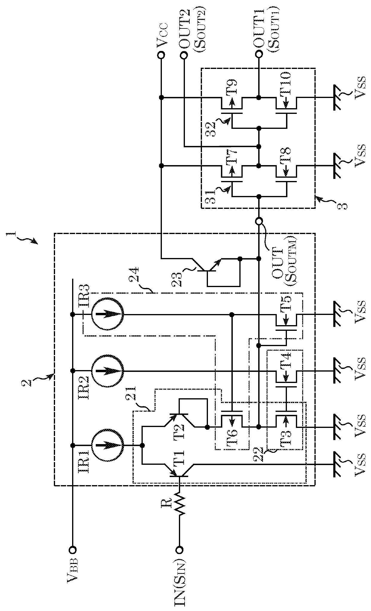
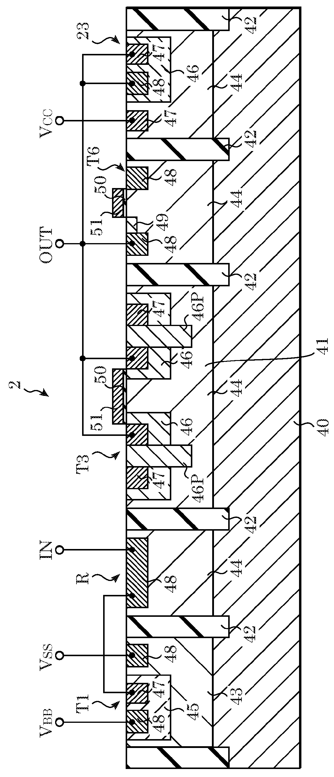
[0026]As illustrated in FIG. 1, a level shifter 1 according to the present exemplary embodiment is driven by a high-voltage first power source voltage VBB supplied from a vehicle mounted battery. The level shifter 1 is configured of a level shifter section 2 and a buffer section 3. In the level shifter 1, output signals SOUT1 and SOUT2 that have been level-shifted from a first power source voltage VBB to lower voltages are output in accordance with an input signal SIN having a voltage lower than the first power source voltage VBB.

[0027]The first power source voltage VBB is, for example, from 8 V to 18 V. The input signal SIN is, for example,...


PUM


Abstract

The present disclosure provides a level shifter including: a level shifter section that is driven by a first power source voltage, and that, in accordance with switching of an input signal of a voltage lower than the first power source voltage, switches an output signal that has been level-shifted, from the first power source voltage to a voltage lower than the first power source voltage; and a threshold voltage changing circuit that, in accordance with a switching direction of the input signal, changes a threshold voltage of the input signal for switching the output signal.

Description

CROSS-REFERENCE TO RELATED APPLICATION[0001]This application claims priority under 35 USC 119 from Japanese Patent Application No. 2016-203701, filed on Oct. 17, 2016, the disclosure of which is incorporated by reference herein.BACKGROUNDTechnical Field[0002]The present disclosure relates to a level shifter.Related Art[0003]Japanese Patent Application Publication (JP-B) No. 5465548 discloses a level shifter that transforms a high voltage supplied from a vehicle mounted battery into a low voltage which is usable in an engine control unit (ECU) or the like. A level shifter section is included in the level shifter. In the level shifter section, in a case in which an input signal is input, an output signal that has been level-shifted from a high voltage to a low voltage is output.[0004]The above level shifter is configured such that, in a case in which an input signal has been input and has reached a specific threshold voltage, an output signal switches immediately in accordance with sw...

Claims


Application Information

Patent Timeline
Patent Type & Authority Applications(United States)
IPC IPC(8): H03K19/08H03K19/003H03K19/018
CPCH03K19/0813H03K19/00307H03K19/01831H03K19/00315H03K19/0944
Inventor MATSUBARA, JUNICHI
Owner KK TOKAI RIKA DENKI SEISAKUSHO
Why Eureka
Try Eureka