Disk device and method of generating signal representing head

Inactive Publication Date: 2006-11-21
HITACHI GLOBAL STORAGE TECH JAPAN LTD
View PDF20 Cites 10 Cited by
  • Summary
  • Abstract
  • Description
  • Claims
  • Application Information

AI Technical Summary

Benefits of technology

[0052]Accordingly, it is an object of the present invention to provide an economical and highly reliable disk device in which the above menti

Problems solved by technology

Operation noise will give an adverse influence to the A/D converter 24.
This results in an increase in manufacturing cost.
This is not a good idea.
If the CPU serial I/O 92 shown in FIG. 2 is used at this time, it would take a longer period of time to read the burst registers so that it is not suitable for fast servo control.
Another problem will occur in this case.
There is a risk that the A/

Method used


Image

  • Disk device and method of generating signal representing head
  • Disk device and method of generating signal representing head
  • Disk device and method of generating signal representing head

Examples


first embodiment

[0114]Now, the present invention will be described with reference to the drawings.

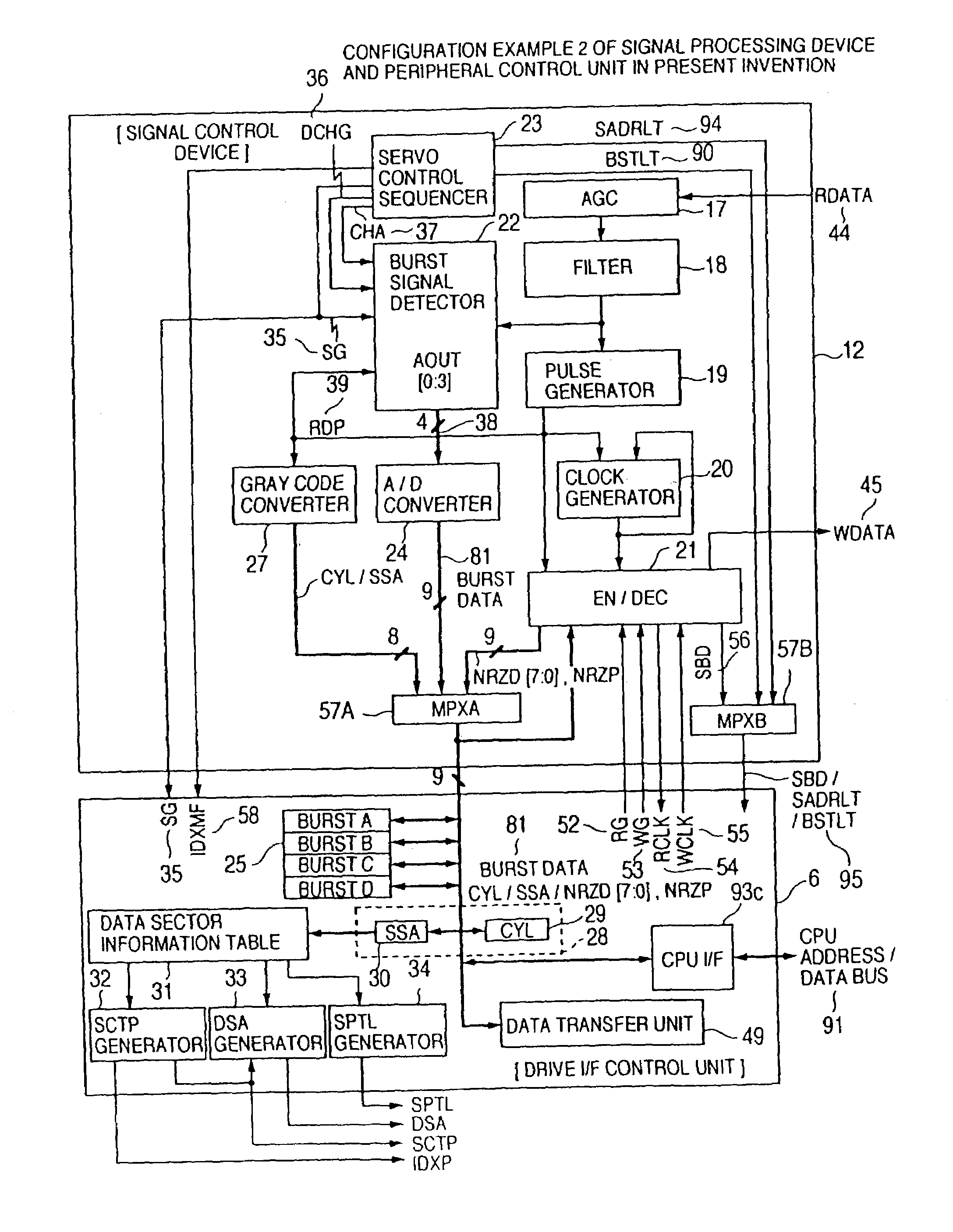
[0115]FIG. 10 shows an example of the circuit configuration of a signal processing device 12, servo control unit 4 and drive I / F control unit 6, to which the present invention is applied. In the signal processing device 12 of FIG. 10, components which are like to those shown in FIG. 3 are designated by like numerals. The signal processing device 12 of the present invention is added with an A / D converter 24 and MPXA (multiplexer) 57A. A reference numeral 81 denotes a burst data which is obtained by A / D converting a burst signal Aout 38.

[0116]In order to feed to the CPU 5 a burst data 81, a digital value which has been converted by the A / D converter 24, said burst data 81 is fed to the drive I / F control unit 6 of the disk control device 2 via a signal line (hereafter referred to as “NRZ data bus 82) for feeding NRZD 50 and NRZP 51, and an MPXA 57A. The drive I / F control unit 6 is provided with a burst re...


PUM


Abstract

A signal processing device for analog-to-digital converting a burst signal has a feature of selecting a data bus to notify a disk control device of a conversion result via an NRZ data bus. The disk control device stores the result of the analog-to-digital conversion of the servo positional signal. The positional signal of a head of the disk device is digitized in a R/W channel. Sampling for digital conversion is performed in only a window which is defined only in the vicinity of peaks of the positional signal. The values of peaks which are obtained by sampling are averaged by an averaging circuit. This enables the influence of noise occurred outside of the window to be eliminated. Although the noise in the window is sampled, its adverse influence is suppressed by the averaging processing.

Description

[0001]This is a continuation application of U.S. Ser. No. 10 / 200,509, filed Jul. 23, 2002, now U.S. Pat. No. 6,563,656; which is a continuation application of U.S. Ser. No. 09 / 716,326, filed Nov. 21, 2000, now U.S. Pat. No. 6,445,522; which is a divisional application of U.S. Ser. No. 08 / 857,171, filed May 15, 1997, now U.S. Pat. No. 6,172,828.BACKGROUND OF THE INVENTION[0002]a) Field of the Invention[0003]The present invention relates to a disk device, and in particular to a circuit for processing servo information and a method of generating a signal representative of the position of a head for reading / writing data in an auxiliary storage of an electronic data processing device using a disk type storage medium.[0004]b) Description of the Related Art[0005]As personal computers have recently been improved in performance and their costs have been reduced, data storage devices, in particular magnetic disk devices, are strongly demanded to provide a large quantity of storage capacity an...

Claims


Application Information

Patent Timeline
IPC IPC(8): G11B5/09G11B5/596G11B20/12G11B20/24G11B21/10
CPCG11B5/59605G11B20/1217G11B20/24G11B21/106G11B2020/1287G11B2020/1298
Inventor TSUNODA, MOTOYASUMIYAZAWA, LEGAL REPRESENTATIVE, YUKIEOGAWA, HITOSHIHORITA, RYUTARONARA, TAKASHINISHINA, MASATOSHIYAMAMOTO, KATSUMIMIYAZAWA, DECEASED, SHOICHI
Owner HITACHI GLOBAL STORAGE TECH JAPAN LTD
Why Eureka
Try Eureka