Integrated circuit with signal assist circuitry and method of operating the circuit

Active Publication Date: 2015-04-02
ARM LTD
View PDF14 Cites 10 Cited by
  • Summary
  • Abstract
  • Description
  • Claims
  • Application Information

AI Technical Summary

Benefits of technology

[0017]In some examples, the integrated circuit may have precharge circuitry which precharges the signal line to the logical high signal level, which can be useful for example if the signal line needs to be at the logical high signal level in time for a particular event within the integrated circuit or the predetermined circuitry. For example, in a memory a bitline may be precharged to the logical high signal level by the precharge circuitry, and then the level on the bitline may either drop to the logical low signal level or remain at the logical high signal level depending on the state of a memory cell being read. The signal assist circuit of the present technique is particularly useful in a circuit having precharge circuitry. When the signal line has been precharged, then any subsequent transition of the signal line to the logical low signal level can be made faster using the second assist circuit of the signal assist circuitry. On the other hand, the first assist circuit will maintain the signal line at the logical high signal level following precharging, so that if there is no event at the predetermined circuitry which causes a pulldown transition, then the signal line will remain at the logical high signal level and will not float. Hence, in both cases the noise tolerance can be improved and performance made faster using the signal assist circuit.
[0018]It can be useful to provide the second assist circuit with a normal mode and a tristate mode. In the normal mode, the second assist circuit may function as discus

Problems solved by technology

This constrains the operating frequency and operating voltage with which the integrated circuit can operate, and so can limit performance or energy efficiency.
This previous approach is less advantageous because the common assist

Method used


Image

  • Integrated circuit with signal assist circuitry and method of operating the circuit
  • Integrated circuit with signal assist circuitry and method of operating the circuit
  • Integrated circuit with signal assist circuitry and method of operating the circuit

Examples


Embodiment Construction

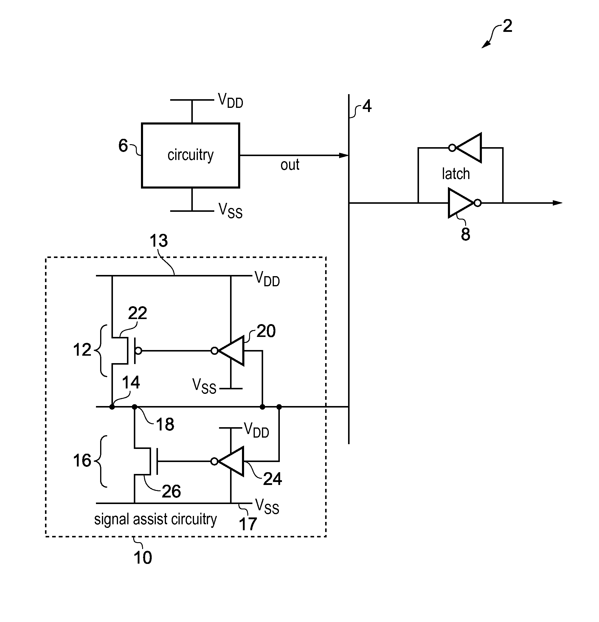
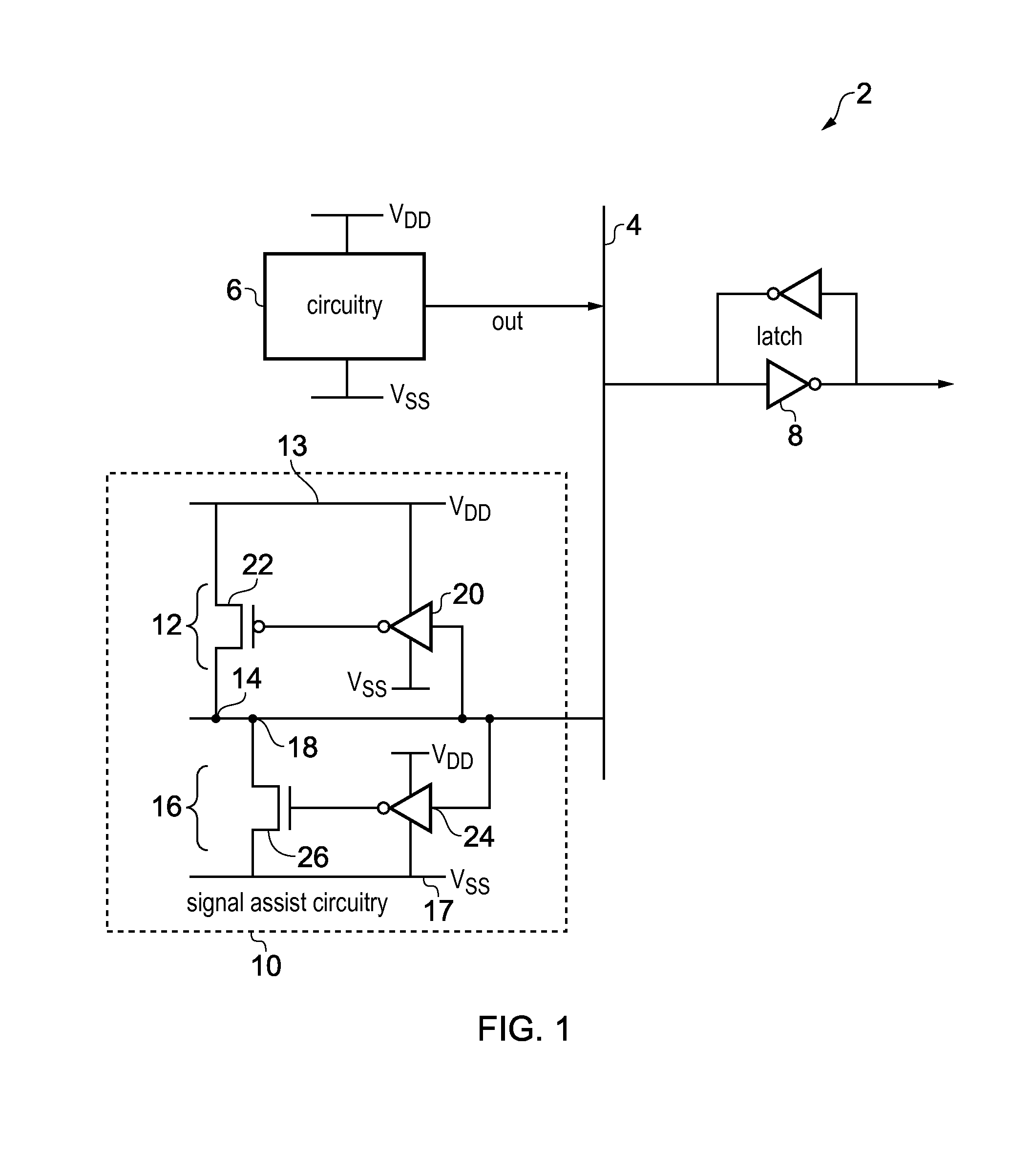
[0041]FIG. 1 schematically illustrates an integrated circuit 2 having a signal line 4 for carrying a signal whose signal level is dependent on an output of predetermined circuitry 6. The predetermined circuitry 6 may comprise any functional circuit for generating an output signal for the signal line 4. For example, the predetermined circuitry 6 may comprise a memory cell or a set of logic gates in a processing unit. The predetermined circuitry 6 need not be part of the integrated circuit 2. In some examples the predetermined circuitry 6 may be an external circuit which is coupled to a signal line 4 within the integrated circuit 2. A latch 8 is provided to capture the signal level on the signal line 4. Other circuits can then read the value of the signal line from the latch 8.

[0042]The operating frequency and voltage of the integrated circuit 2 are limited by several factors associated with the signal on the signal line 4. Firstly, when the predetermined circuitry 6 changes states so...


PUM


Abstract

An integrated circuit has signal assist circuitry for assisting with pulling a signal on the signal line towards the logical low or high signal level. The signal assist circuitry comprises first and second assist circuits. The first assist circuit couples the signal line to the logical high signal level following a pullup transition of the signal and provides a floating signal level following a pulldown transition, while the second assist circuit provides the floating signal level following the pullup transition and provides the logical low signal level following the pulldown transition. By providing complementary first and second assist circuits, each circuit can be optimized for the opposite transition to achieve improved performance or power consumption.

Description

TECHNICAL FIELD[0001]The present technique relates to the field of integrated circuits. More particularly, the present technique relates to an integrated circuit having signal assist circuitry for assisting with pulling a signal on a signal line to a logical low signal level or logical high signal level.TECHNICAL BACKGROUND[0002]An integrated circuit may have a latch circuit for capturing the signal level of a signal line within the integrated circuit. For example, in a memory the latch may capture the signal on a bitline for reading a data value from a memory cell. To ensure correct circuit operation, following a transition of the signal level on the signal line it is important that the latch captures the new signal level before the signal level changes for a following cycle. This constrains the operating frequency and operating voltage with which the integrated circuit can operate, and so can limit performance or energy efficiency.[0003]A signal assist circuit may be provided to h...

Claims


Application Information

Patent Timeline
IPC IPC(8): H03K19/017H03K19/094H03K19/00
CPCH03K19/01721H03K19/09429H03K19/0013G11C7/12G11C11/419H03K19/0963
Inventor SRINATH, SRINIVASANASHOK, AMBICABOHRA, FAKHRUDDIN ALI
Owner ARM LTD
Why Eureka
Try Eureka