
Medical observation device, surgical observation device, and medical observation system

Active Publication Date: 2018-04-26
SONY OLYMPUS MEDICAL SOLUTIONS
View PDF66 Cites 6 Cited by
  • Summary
  • Abstract
  • Description
  • Claims
  • Application Information

AI Technical Summary

Benefits of technology

The patent allows for a smaller support unit structure, which can be achieved through various means. In simpler terms, this patent allows for a smaller size of the support unit.

Problems solved by technology

If the structure of the support unit 801 that supports the microscope unit 802 is large in order for the surgeon to perform various procedures on the surgical site, there may be interference between the hands of the surgeon performing the procedure and the support unit 801, which may hinder work from being performed smoothly.
Therefore, assuming a case in which surgery is performed using an electronic imaging observation device having actuators at joint units of a support unit, it is conceivable that it will be difficult to ensure the workspace and field of view of the surgeon.
However, until now, downsizing of the structure of the distal end region of the support unit of an observation device having actuators in joint units of a support unit has not been sufficiently examined.
However, in a power transmission mechanism that uses such a link or wire or the like, the transmissible rotation angle may be limited.
In order to be able to capture an image of an object to be observed from any direction, the range of motion of the microscope unit 110 needs to be as wide as possible, so it is undesirable that the rotation angle of the second axis O2 be limited in this way.
However, the actuator 322 configured to be able to respond to this kind of advanced control is relatively expensive, and has a tendency to become large, particularly in the radial direction (the in-plane direction perpendicular to the drive shaft).
As a result, the structure near the microscope unit 110 may not be able to be effectively made smaller.
For example, in the unlikely event that power is lost for some reason, if the motor 341 is connected to a downstream member by the clutch 343, rotation of the second joint unit 220 will be locked, and the support unit 120 will be unable to be moved manually, which may make it difficult to continue surgery or an examination.
Consequently, the surgeon 701 may not be able to perform work smoothly.
Therefore, the configuration of the power transmission mechanism 330 may become complicated and the cost may also end up increasing.

Method used


Image

  • Medical observation device, surgical observation device, and medical observation system
  • Medical observation device, surgical observation device, and medical observation system
  • Medical observation device, surgical observation device, and medical observation system

Examples


first embodiment

2. First Embodiment

(2-1. Structure of Observation System and Observation Device)

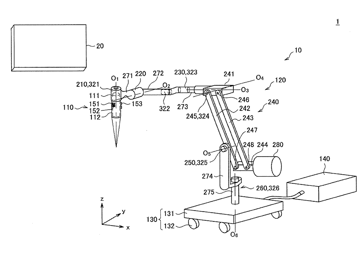
[0061]The structure of an observation system according to a first embodiment of the present disclosure, and an observation device that forms the observation system, will be described with reference to FIG. 4. FIG. 4 is a view illustrating a configuration example of the observation system according to the first embodiment.

[0062]Referring to FIG. 4, the observation system 1 according to the first embodiment includes an observation device 10 that supports a microscope unit 110 and captures an image of a surgical site of a patient with the microscope unit 110, and a display device 20 that displays the image of the surgical site captured by the observation device 10. During surgery, the surgeon observes the surgical site and performs various procedures on the surgical site, while referring to the image captured by the observation device 10 and displayed on the display device 20.

(Display Device)

[0063]As discus...

second embodiment

3. Second Embodiment

[0165]A second embodiment of the present disclosure will now be described. In the second embodiment as well, an observation device in which the structure of the distal end region is smaller can be realized by arranging the second joint unit away from the actuator that applies driving force with respect to rotation about the second axis O2 that is the rotational axis of the second joint unit, similar to the first embodiment. However, in the second embodiment, the structure of the power transmission mechanism that transmits the driving force of the actuator to the second joint unit differs from the structure in the first embodiment. In the second embodiment, the structure other than the structure of the power transmission mechanism may be similar to the structure in the first embodiment, so in the description of the second embodiment below, mainly those matters that differ from the first embodiment will be described. A detailed description of matter similar to matt...


PUM


Abstract

Provided is a medical observation device including an imaging unit configured to capture an image of an object to be observed, and output a video signal, and a support unit configured with a plurality of arm units rotatably connected to each other via joint units, and configured to support the imaging unit. An actuator that applies driving force with respect to rotation about a rotational axis of at least one joint unit that defines an attitude of the imaging unit, among a plurality of the joint units that form the support unit, is provided. The at least one joint unit and the actuator are arranged separated from each other, and are connected together via a power transmission mechanism that transmits rotary movement between two rotational axes that are substantially orthogonal to each other.

Description

TECHNICAL FIELD[0001]The present disclosure relates to a medical observation device, a surgical observation device, and a medical observation system.BACKGROUND ART[0002]In recent years, support arm devices for assisting with surgery and examinations have come to be used in medical settings. For example, an optical observation device (observation device) in which a magnifying optical system for performing magnified observation of an extremely small portion of a surgical site of a patient is provided on a distal end of a support unit of a support arm device. When performing surgery using an optical observation device, an operator such as a doctor performs the surgery while directly observing the surgical site through an eyepiece provided with the magnifying optical system.[0003]With such an observation device, various technologies for realizing better operability are being developed by devising arrangements and configurations of power transmission mechanisms such as gears that transmi...

Claims


Application Information

Patent Timeline
IPC IPC(8): A61B90/25A61B90/00G02B21/36
CPCA61B90/25A61B90/361G02B21/362A61B2090/506A61B2090/504A61B2090/371A61B2034/2059G02B7/001G02B21/0012
Inventor KAMATA, YOSHIYUKIKOBAYASHI, MOTOAKITAMURA, SHIGERUHIROSE, KENJI
Owner SONY OLYMPUS MEDICAL SOLUTIONS
Features
  • Generate Ideas
  • Intellectual Property
  • Life Sciences
  • Materials
  • Tech Scout
  • Unparalleled Data Quality
  • Higher Quality Content
  • 60% Fewer Hallucinations
Learn More