Underwater drone with capacity of fishing, rapidly moving and wireless remote control

a wireless remote control and underwater drone technology, applied in underwater equipment, special-purpose vessels, instruments, etc., can solve the problems of resistance of water to underwater drones from rapidly moving, lack of entertainment, and inconvenient carrying and storage of cables, so as to reduce resistance and increase the interest of underwater drones. , the effect of rapid movemen

Active Publication Date: 2018-04-26
POWERVISION TECH
View PDF0 Cites 11 Cited by
  • Summary
  • Abstract
  • Description
  • Claims
  • Application Information

AI Technical Summary

Benefits of technology

[0032]In summary, the underwater drone of the present invention includes the horizontal propeller module and the vertical propeller module to respectively provide the drone body with a horizontal proceeding force and a vertical lifting or diving force. Furthermore, the underwater drone of the present invention includes the horizontal channel and the vertical channel, which allow the water to pass through for reducing resistance when the underwater drone moves forwards, upwards or downwards. As a result, the underwater drone is capable of rapidly moving. Furthermore, the underwater drone of the present invention can be equipped with the buoy member with the antenna portion of the communication module disposed therein. As a result, the antenna portion of the communication module is able to establish the connection with the remote control in a wireless manner without being affected by signal decay by water. Furthermore, the underwater drone of the present invention can be equipped with the fishing device, the fish finding device and the image capturing module. It allows the user to find fish, capture images or recording videos, and catch the fish, which results in increase of interests of use of the underwater drone.

Problems solved by technology

However, resistance of water resists the underwater drone from moving rapidly.
However, the cable often wraps with water plants or is stuffed by objects, such as stones, underwater, and the cable is not convenient for carrying and storing.
In addition, the conventional underwater drone is not able to carry stuff, such as fishing equipment, which results in lack of entertainment.

Method used


Image

  • Underwater drone with capacity of fishing, rapidly moving and wireless remote control
  • Underwater drone with capacity of fishing, rapidly moving and wireless remote control
  • Underwater drone with capacity of fishing, rapidly moving and wireless remote control

Examples


first embodiment

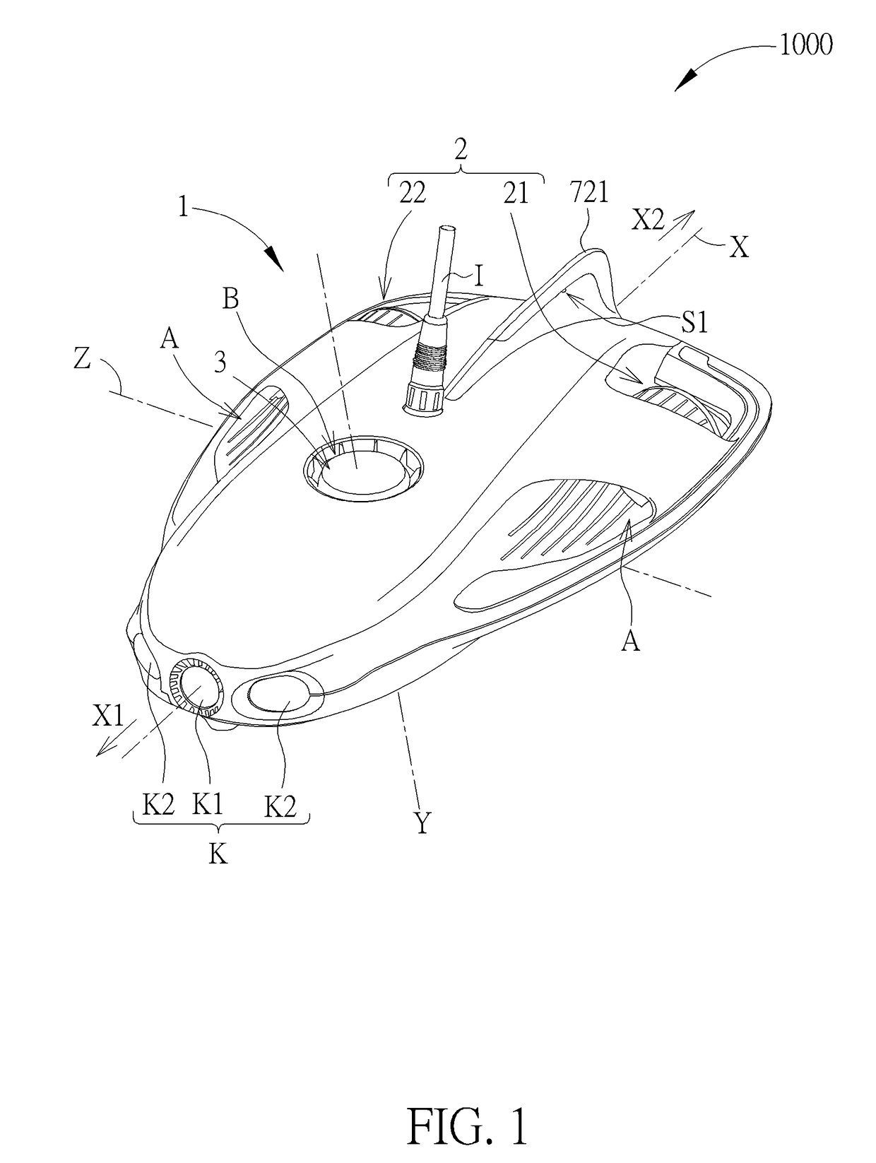
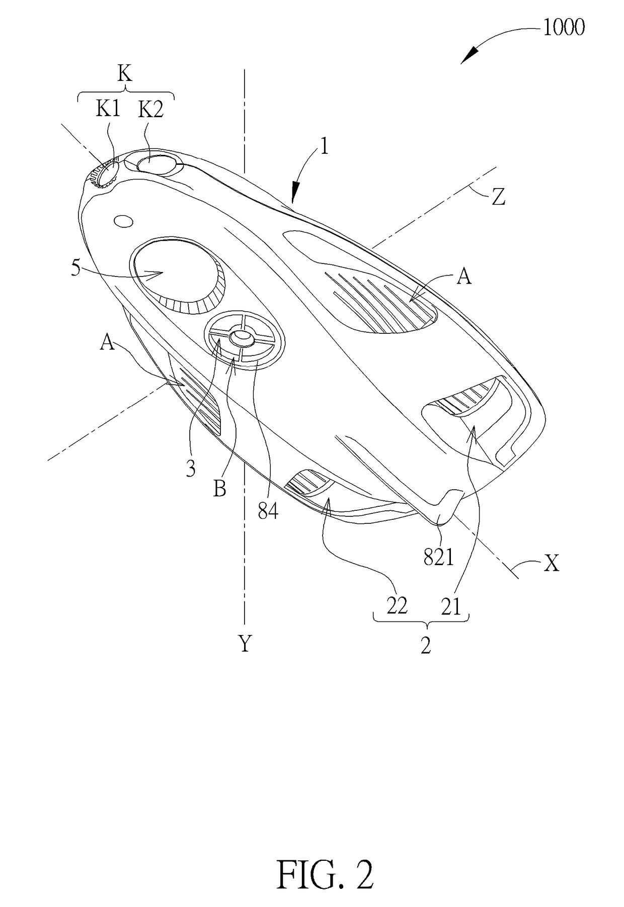
[0062]Furthermore, the vertical propeller module 3 disposed on the drone body 1 and oriented substantially parallel to the vertical axis Y. The vertical propeller module 3 is for driving the drone body to rotate about a lateral axis Z perpendicular to the longitudinal axis X and the vertical axis Y. The lateral axis Z is analogy for a pitch axis of the airplane. Please refer to FIG. 5. FIG. 5 is a side view of the underwater drone 1000 according to the present invention. As shown in FIG. 5, a distance D1 between the horizontal propeller module 2 and the drone rear end 11 is smaller than a distance D2 between the horizontal propeller module 2 and the drone front end 10. The vertical propeller module 3 is disposed between the drone front end 10 and a gravity center G of the underwater drone 1000 along the longitudinal axis X. In other words, the vertical propeller module 3 is disposed closer to the drone front end 10 than the drone rear end 11. The disposal of the vertical propeller m...

third embodiment

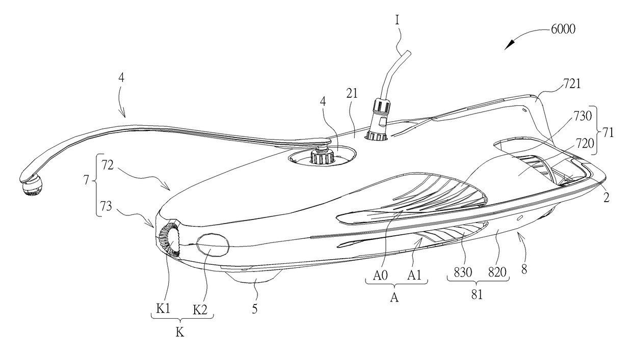
[0079]Please refer to FIG. 12. FIG. 12 is a diagram of an underwater drone 3000 according to the present invention. As shown in FIG. 12, the major difference between the underwater drone 3000 and the aforesaid underwater drone 2000 is that the underwater drone 3000 further includes a wire rolling module L. The wire rolling module L is installed on the drone body 1, and the wire rolling module L is for rewinding or releasing the wire J. In this embodiment, the wire rolling module L includes a rolling device L0 and a rolling controller L1. The rolling device L0 is disposed on the drone body 1 and protrudes from a surface of the drone body 1. The rolling controller L1 is coupled to the rolling device L0 and the central processing unit 6. The rolling controller L1 is controlled by the central processing unit 6, so as to drive the rolling device L0 to rewind or release the wire J.

[0080]In this embodiment, the underwater drone 3000 can further include a depth sensor for sensing a depth in...

fourth embodiment

[0081]Please refer to FIG. 13. FIG. 13 is a diagram of an underwater drone 4000 according to the present invention. As shown in FIG. 13, the major difference between the underwater drone 4000 and the aforesaid underwater drone 3000 is that there is a cavity 12 formed on the drone body 1 of the underwater drone 4000, and the rolling device L0 of the wire rolling module L is disposed inside the cavity 12 instead of protruding from the surface of the drone body 1, which avoids the rolling device L0 from damage due to collision of the rolling device L0 with the objects, such as water plants and so on. Components with denoted in this embodiment identical to those in the aforesaid embodiment have identical structures and functions, and further description is omitted herein for simplicity.


PUM


Abstract

An underwater drone is disclosed. The underwater drone includes a horizontal propeller module and a vertical propeller module to respectively provide a drone body with a horizontal proceeding force and a vertical lifting or diving force. The underwater drone includes a horizontal channel and a vertical channel, which allow the water to pass through for reducing resistance when the underwater drone moves forwards, upwards or downwards. The underwater drone is equipped with a buoy member with an antenna portion of a communication module disposed therein. The underwater drone is equipped with the fishing device, the fish finding device and the image capturing module. Therefore, the underwater drone is capable of fishing, rapidly moving and wireless remote control.

Description

CROSS REFERENCE TO RELATED APPLICATIONS[0001]This application is a continuation in part of PCT / CN2016 / 093121, filed on Aug. 3, 2016.[0002]This application claims the benefit of CN 201710004597.0, which was filed on Jan. 4, 2017, and the benefit of CN 201720356181.0, which was filed on Apr. 6, 2017, and is incorporated herein by reference.BACKGROUND OF THE INVENTION1. Field of the Invention[0003]The present invention relates to an underwater drone, and more particularly, to an underwater drone with capacity of fishing, rapidly moving and wireless remote control.2. Description of the Prior Art[0004]Recently, an underwater drone which is capable of diving and moving underwater has been gradually in entertainment purpose of people's daily life, such as taking photos and recording videos underwater. However, resistance of water resists the underwater drone from moving rapidly. Furthermore, the conventional underwater drone is equipped with a cable connected therewith for communication wi...

Claims


Application Information

Patent Timeline
Patent Type & Authority Applications(United States)
IPC IPC(8): B63G8/00A01K87/00B63B22/00B63G8/16B63G8/39G01S15/96
CPCH04W76/10B63G8/001A01K87/00B63B22/003B63G8/16B63G8/39G01S15/96B63G2008/007B63G2008/004B63B2213/02G01S19/13H04N7/185H04W76/02
Inventor ZHENG, WEIFENGHE, ZHIXIONGZHENG, DIWU, HAILIANGTANG, JIEWU, GUANGZHANG
Owner POWERVISION TECH
Why Eureka
Try Eureka