Range sensor and solid-state imaging device
a solid-state imaging and sensor technology, applied in the field of range sensor and solid-state imaging devices, can solve the problems of increasing the load capacitance of a plurality of transfer gates connected in parallel, increasing the entire power consumption, and dark current, and achieves high sensitivity, high-speed modulation, and large light receiving area
- Summary
- Abstract
- Description
- Claims
- Application Information
AI Technical Summary
Benefits of technology
Problems solved by technology
Method used
Image
Examples
first embodiment
Modified Example of First Embodiment
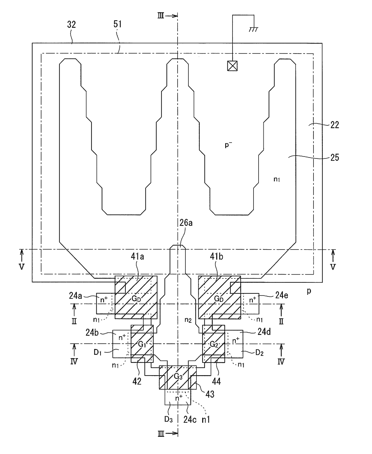
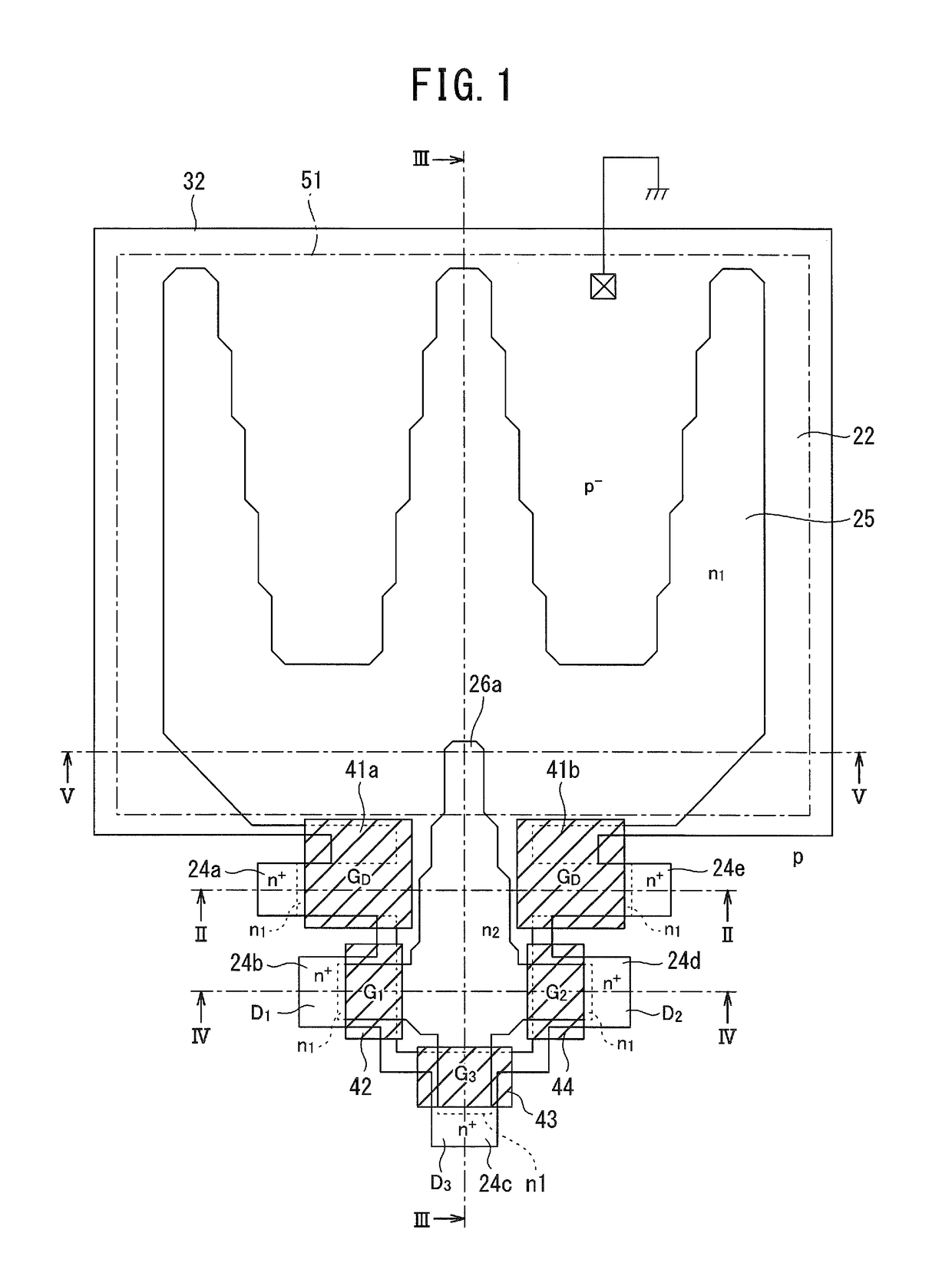
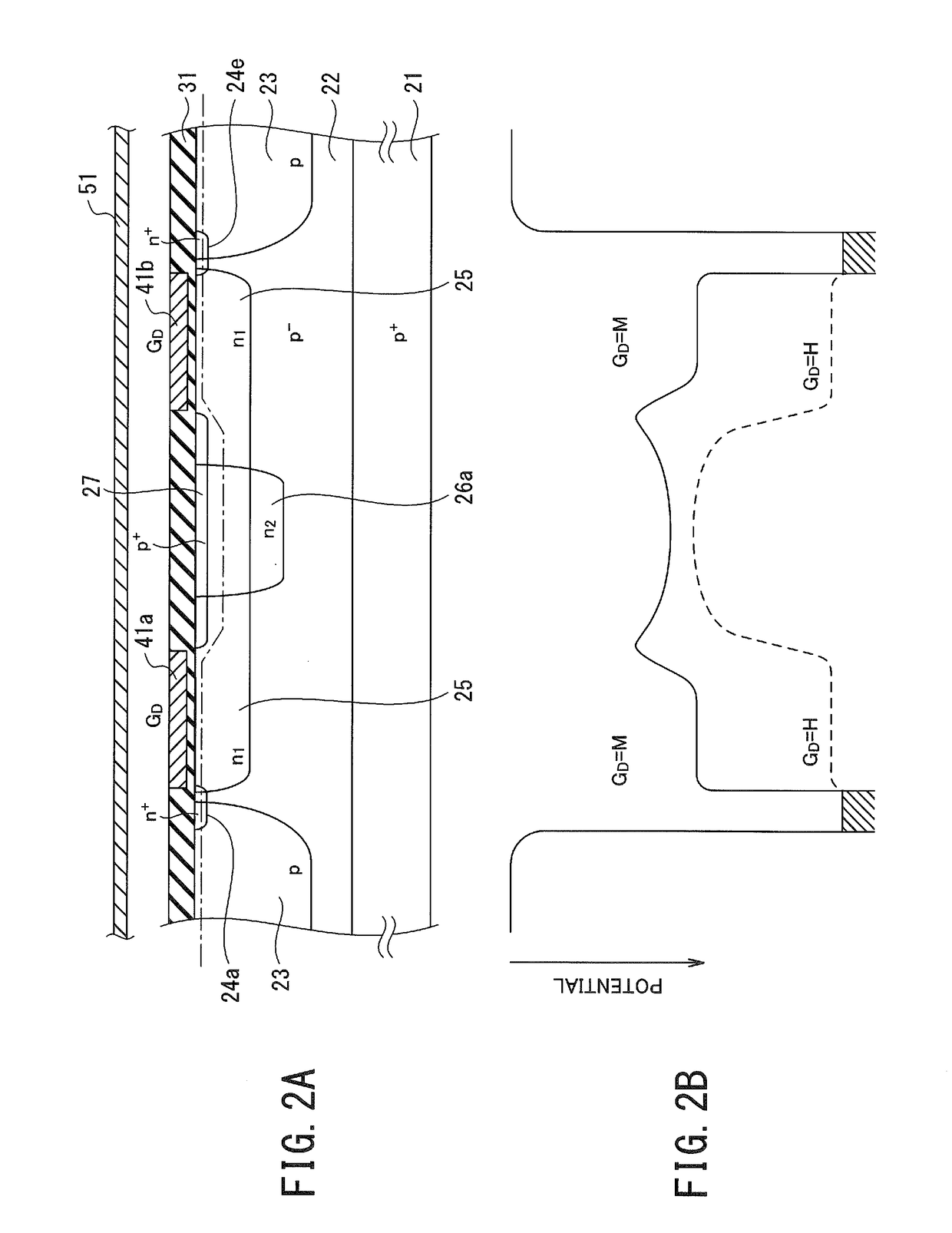
[0114]As shown in the schematic plan view from above of the principal part in FIG. 13, a range sensor according to a modified example of the first embodiment is a lock-in pixel including a shielding plate 51 having an aperture defining a light-receiving area. Although not shown in the drawings, the range sensor according to the modified example of the first embodiment has the same cross sections as shown in FIG. 2 to FIG. 4 and includes: a pixel layer 22 made of a semiconductor of a first conductivity type (p-type); the shielding plate 51 having the aperture and provided above the pixel layer 22 to define the light-receiving area on the pixel layer 22 below the aperture; a surface-buried region 25 of a second conductivity type (n-type) selectively buried in the upper portion of the pixel layer 22 to implement a photodiode in the light-receiving area by forming a junction with the pixel layer 22, and extending from the light-receiving area toward p...
second embodiment
[0121]A range sensor according to the second embodiment of the present invention is a lock-in pixel including a shielding plate 51 having an aperture indicated by the dashed-dotted line in FIG. 15 to define a light-receiving area. The range sensor according to the second embodiment fundamentally has the same structure as the range sensor according to the first embodiment, as shown in the cross-sectional views of FIG. 2 to FIG. 4, and serves as a lock-in pixel including: a pixel layer 22 made of a semiconductor of a first conductivity type (p-type); the shielding plate 51 having the aperture and provided above the pixel layer 22 to define the light-receiving area on the pixel layer 22 below the aperture; a surface-buried region 25 of a second conductivity type (n-type) selectively buried in the upper portion of the pixel layer 22 to implement a photodiode in the light-receiving area by forming a junction with the pixel layer 22, and extending from the light-receiving area toward plur...
third embodiment
[0133]A range sensor according to the third embodiment of the present invention is a lock-in pixel including a first surface-buried region 25u and a second surface-buried region 25v opposed in an interdigital manner inside a light-receiving area defined by a shielding plate 51 having a single aperture indicated by the dashed-dotted line as shown in the schematic plan view from above of the principal part in FIG. 16. Reference numeral 32b shown in FIG. 16 denotes an edge of a field insulating film. Namely, an area surrounded by the edge 32b defines an active area of the lock-in pixel. The range sensor according to the third embodiment thus includes two surface-buried regions in one pixel. As in the case shown in the cross sections of FIG. 2A, FIG. 3A and FIG. 4A, a p-type well region 23 is buried below the field insulating film (not shown).
[0134]When focused on the first surface-buried region 25u provided in the light-receiving area on the upper side in FIG. 16, the range sensor acco...
PUM
 Abstract
Description
Claims
Application Information
 - R&D
- Intellectual Property
- Life Sciences
- Materials
- Tech Scout
- Unparalleled Data Quality
- Higher Quality Content
- 60% Fewer Hallucinations
Browse by: Latest US Patents, China's latest patents, Technical Efficacy Thesaurus, Application Domain, Technology Topic, Popular Technical Reports.
© 2025 PatSnap. All rights reserved.Legal|Privacy policy|Modern Slavery Act Transparency Statement|Sitemap|About US| Contact US: help@patsnap.com


