
LED ceiling lamp

a technology of led ceiling lamps and led tubes, which is applied in the direction of semiconductor devices for light sources, lighting and heating apparatus, lighting support devices, etc., can solve the problems of large fluorescent tubes, short service life of fluorescent tubes, and high mercury pollution, and achieves long service life, easy assembly and repair, and long service life

Active Publication Date: 2018-05-03
XIAMEN PVTECH
View PDF6 Cites 1 Cited by
  • Summary
  • Abstract
  • Description
  • Claims
  • Application Information

AI Technical Summary

Benefits of technology

The patent describes an LED ceiling lamp that can be customized in length and designed for heat dissipation and power requirements. It has a long service life, is easy to assemble and repair, and provides a high light emitting rate and efficiency of power source.

Problems solved by technology

However, the fluorescent tube is large.
Moreover, heavy mercury pollution is generated in manufacture, use and disposal processes, which is a potential heavy metal pollution source in the environmental protection.
The service life of the fluorescent tube is very short, only about 1000 hours.
Obviously, the electric energy is wasteful, and the burden on the natural environment is heavy.
However, the LED tubular lamps of this type have many disadvantages.
For example, the resistance to pressure is not enough, the requirement on a driving power source is high, the cost is high, and the safety performance is low.
Thus, tubular lamps of this type usually cannot meet the requirement of users, and the practicability is not good enough.
However, the heat dissipation effect is poor, and the LED plate cannot be made in a large size.
Moreover, the service life is short.
Additionally, the structure of the LED tubes in the market is too complex, and the disassembly is too difficult for users.

Method used


Image

  • LED ceiling lamp
  • LED ceiling lamp
  • LED ceiling lamp

Examples


Embodiment Construction

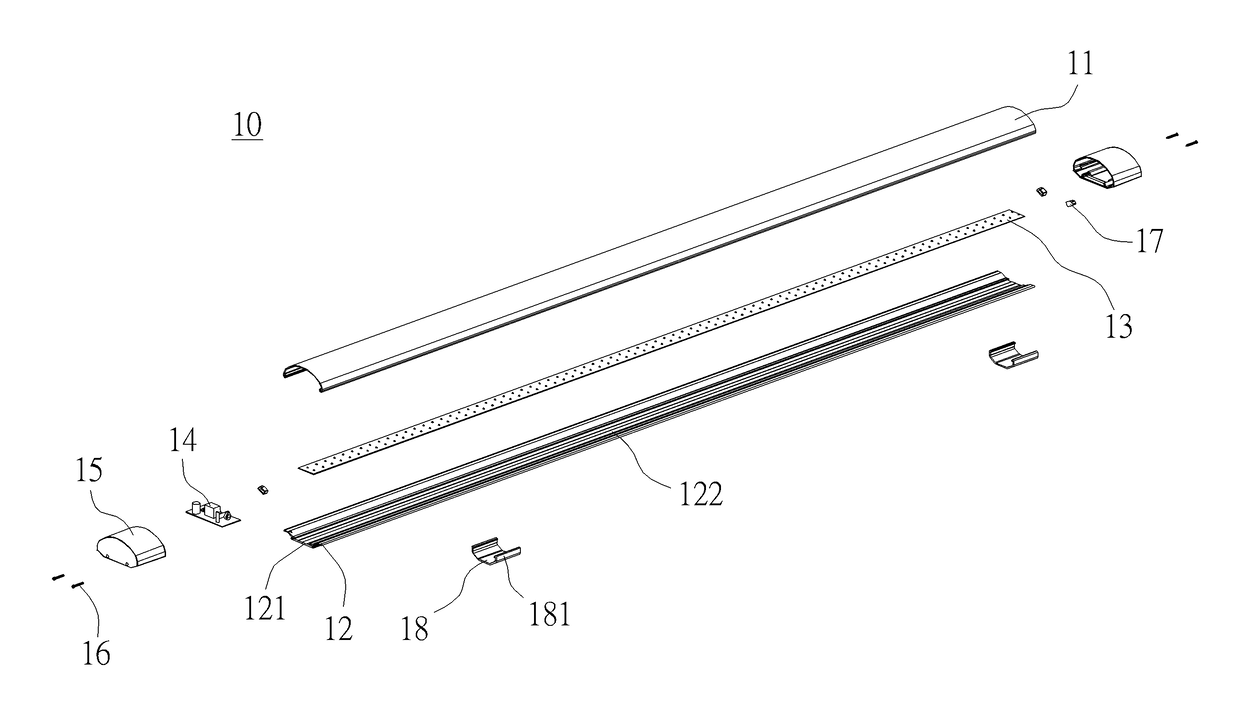
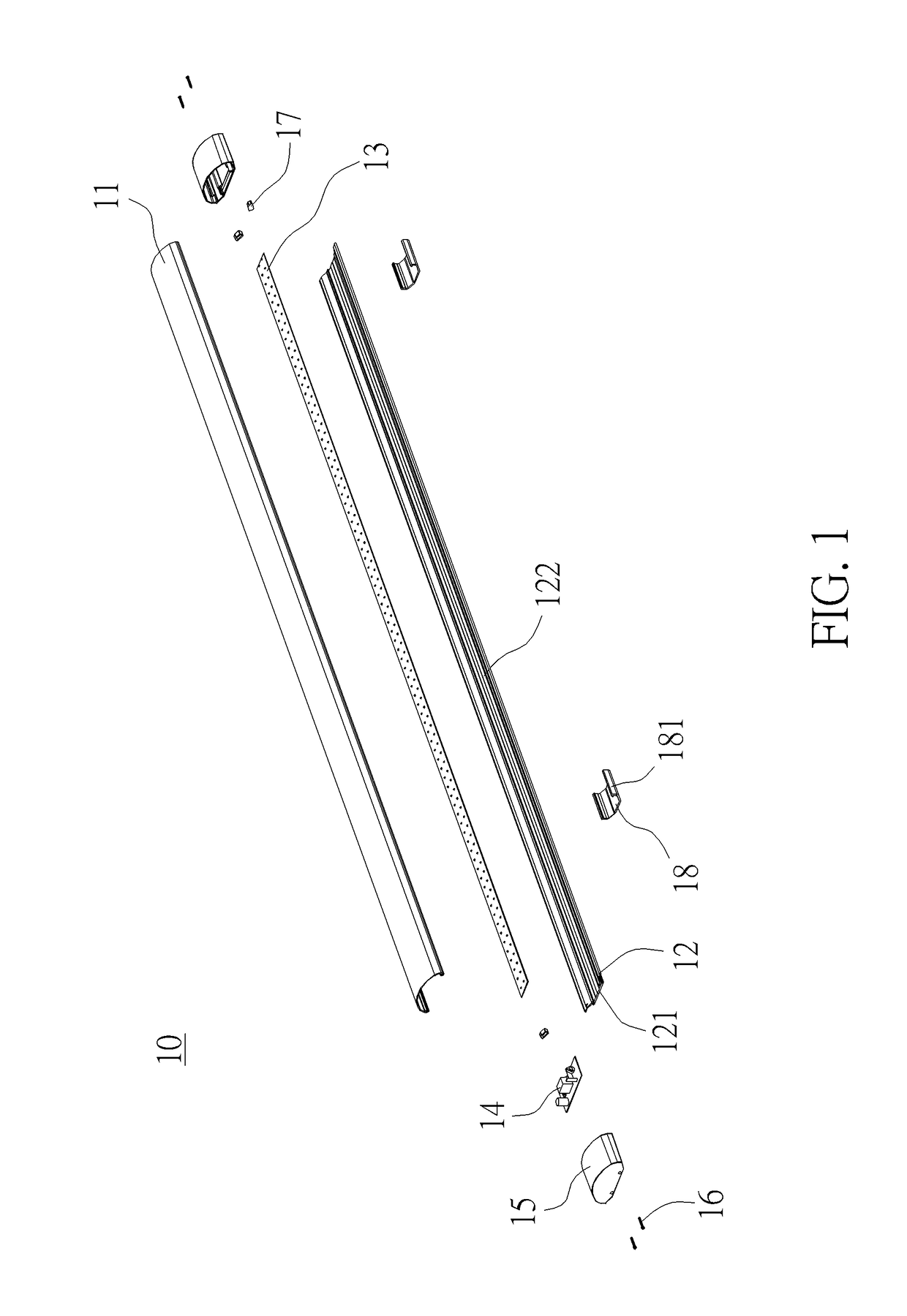
[0021]FIG. 1 is an explode diagram of a LED ceiling lamp in an embodiment. As shown in FIG. 1, a LED ceiling lamp 10 includes an elongated light cover 11, an elongated housing 12, a light source plate 13, a power source seat 14, and two end covers 15.

[0022]The LED ceiling lamp 10 includes an elongated light cover 11 and an elongated housing 12. The elongated housing 12 includes a fastening slot 121. Two side portions of the elongated housing 12 are connected with the elongated light cover 11. The light source plate 13 is secured between the elongated light cover 11 and the elongated housing 12. The power source seat 14 is electronically connected to the light source plate 13. The power source seat 14 is secured on the fastening slot 121. Two end covers 15 are connected with two ends of the elongated light cover 11 and two ends of the elongated housing 12, respectively.

[0023]In an embodiment, the elongated light cover 11 is made of light-transmitting plastic, such as polycarbonate (P...


PUM


Abstract

A LED ceiling lamp is provided. The LED ceiling lamp comprises: an elongated light cover; an elongated housing including a fastening slot and two side portions connected with the elongated light cover; a light source plate secured between the elongated light cover and the elongated housing; a power source seat electronically connected to the light source plate and being secured on the fastening slot; and two end covers connected with two ends of the elongated light cover and two ends of the elongated housing, respectively. The length of the LED ceiling lamp is various according to the requirement. The heat dissipation effect is well. The power can be designed according to requirements. The service life is long. The LED ceiling lamp is easily assembled and repaired. The light emitting rate is high. The light emitting efficiency of the power source is high.

Description

BACKGROUND OF THE INVENTION1. Field of the Invention[0001]The invention relates to a light-emitting diode (LED) ceiling lamp and, more particularly, relates to a LED ceiling lamp for a T5 tube which has good heat dissipation effect and is convenient to be assembled.2. Description of the Prior Art[0002]A fluorescent tube is a necessary and widely used lighting source. However, the fluorescent tube is large. Moreover, heavy mercury pollution is generated in manufacture, use and disposal processes, which is a potential heavy metal pollution source in the environmental protection. The service life of the fluorescent tube is very short, only about 1000 hours. Only ten percent of the received electric energy can be converted into light energy while ninety percent is converted into useless heat energy to be dissipated into the air. Obviously, the electric energy is wasteful, and the burden on the natural environment is heavy.[0003]LED has a lot of advantages, such as environmental protecti...

Claims


Application Information

Patent Timeline
Patent Type & Authority Applications(United States)
IPC IPC(8): F21S4/28F21V15/01
CPCF21S4/28F21Y2115/10F21V15/01F21V3/02F21V15/015F21V19/0045F21V21/025F21V23/004F21V29/507F21V29/89F21Y2105/10
Inventor LU, FUXINGLAI, RUICHA
Owner XIAMEN PVTECH
Features
  • Generate Ideas
  • Intellectual Property
  • Life Sciences
  • Materials
  • Tech Scout
  • Unparalleled Data Quality
  • Higher Quality Content
  • 60% Fewer Hallucinations
Learn More