Driver circuit for the operation of a relay

a technology of relays and drive circuits, which is applied in the direction of relays, dc-dc conversion, transportation and packaging, etc., can solve the problems of high production and procurement costs, complex pwm signal drives, and capacitors that have a negative influence on the overall system life, so as to achieve the effect of efficient relay operation and easy realization as an integrated componen

Active Publication Date: 2018-05-03
SAMSUNG SDI CO LTD
View PDF0 Cites 2 Cited by
  • Summary
  • Abstract
  • Description
  • Claims
  • Application Information

AI Technical Summary

Benefits of technology

[0005]In embodiments of the present invention, various components may be omitted within, for example, a battery system, because a relay may be operated by using a system basis chip that is already implemented within (e.g., included in) the system. Thus, no additional PWM signal drive needs to be provided to operate the relay, thereby increasing the overall system lifetime, and thereby substantially reducing the cost of production and procurement of the driver circuit.
[0020]Moreover, a method for the operation of a relay including a driver circuit is provided according to embodiments of the present invention. The method includes closing the first switch for a period of time T to close the relay, closing the second switch after the period of time T, and opening the first switch after the second switch is closed while maintaining the second switch in the closed state. Such a method allows for the efficient operation of the relay by using the PRE-voltage of the system basis chip.

Problems solved by technology

Such capacitors may have a negative influence on the overall system lifetime because they are prone to a multitude of effects causing aging and degradation.
Furthermore, the design of such PWM signal drives is complex, and the PWM signal drives include a plurality of components, to provide at least the aforementioned filtering, which results in high costs of production and procurement.
Moreover, a PWM signal of, for example, 20 kHz may also negatively influence the EMC performance of, for example, a battery system.

Method used


Image

  • Driver circuit for the operation of a relay
  • Driver circuit for the operation of a relay
  • Driver circuit for the operation of a relay

Examples


first embodiment

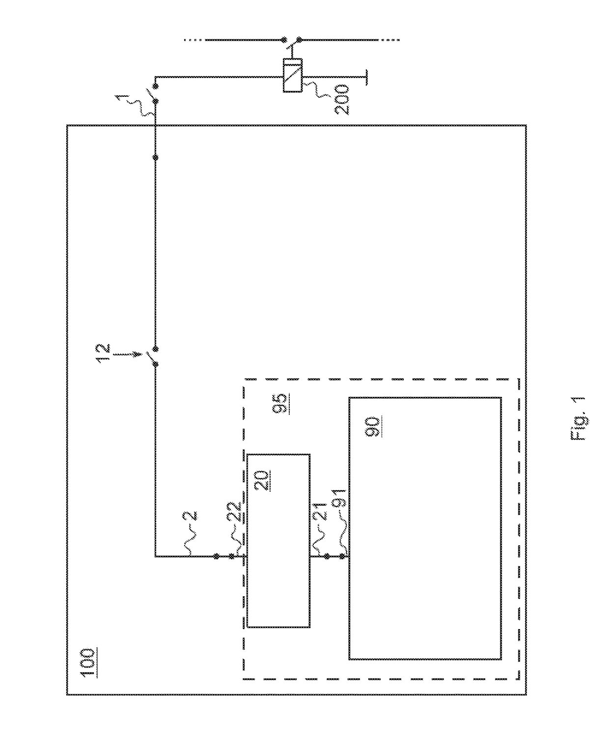
[0030]In the first embodiment, the system basis chip 90 and the buck boost converter 20 are provided within a single integrated circuit 95. For example, the system basis chip 90 and the buck boost converter 20 are provided on the same, single die and form a single integrated component. At the output terminal 91, the system basis chip 90 outputs an output voltage to the input 21 of the buck boost converter 20. Therefore, the system basis chip 90 provides an input voltage for the buck boost converter 20, the buck boost converter 20 being adapted to convert the input voltage at the input 21 into a driving voltage for the relay 200 and to provide this driving voltage at the first output 22 thereof.

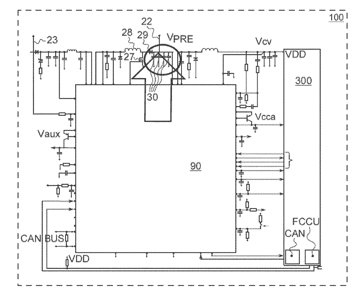
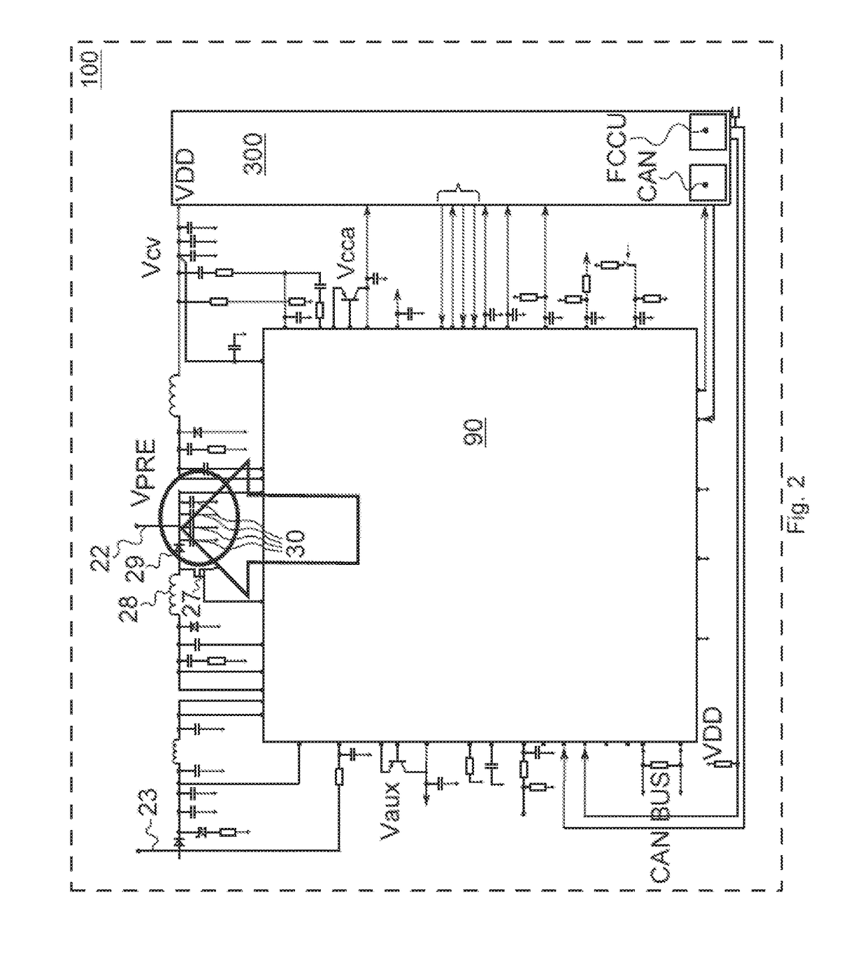
[0031]In FIGS. 2 and 3, different parts of a second embodiment of a driver circuit 100 are shown. In FIG. 2, a system basis chip 90 with a buck boost converter 20 forming a first part of the driver circuit 100 according to the second embodiment of the invention is shown. The first part of the ...

second embodiment

[0034]The PRE-voltage VPRE is also used as a basis supply voltage for the microcontroller 300. For example, the PRE-voltage VPRE is also used as a supply voltage, or as one of a plurality of different supply voltages, for the microcontroller 300. In the second embodiment, the system basis chip 90 is also adapted to provide other supply voltages for the microcontroller 300. For example, the system basis chip 90 includes a boost converter that is adapted to provide a core voltage of Vcv=1.25V. Furthermore, the system basis chip 90 also includes various (e.g., various different) low-dropout regulators (LDOs) adapted to provide a voltage Vaux=3.3V and a voltage Vcca=5V.

[0035]In the second embodiment, the buck boost converter 20 includes a second output 23 that is electrically connected to a second voltage input of the driver circuit 100, which will be described in greater detail hereinafter. The buck boost converter 20 is adapted to provide a second voltage V2 at the second output 23 of...


PUM


Abstract

A driver circuit configured to control an operation of a relay includes: a voltage output electrically connected with the relay; a first voltage input selectively electrically connected to the voltage output; a buck boost converter including an input and a first output; and a system basis chip including an output terminal connected to the input of the buck boost converter and configured to provide a voltage. The first output of the buck boost converter is electrically connected to the first voltage input.

Description

CROSS-REFERENCE TO RELATED APPLICATION[0001]This patent application claims priority to and the benefit of European Patent Application No. 16196288.1, filed on Oct. 28, 2016 in the European Patent Office, the disclosure of which is incorporated herein by reference herein in its entirely.BACKGROUND1. Field[0002]Aspects of embodiments of the present invention relate to a driver circuit for the operation of a relay.2. Related Art[0003]In battery systems, for example in battery systems of automotive vehicles, pulse width modulated (PWM) signals are often used to drive relays in a so-called low power mode, which is often also referred to as an economic mode. PWM signal drives for relays generally include relatively large filters at an input of the power supply of the drives that generally include electrolytic capacitors. Such capacitors may have a negative influence on the overall system lifetime because they are prone to a multitude of effects causing aging and degradation. Furthermore, ...

Claims


Application Information

Patent Timeline
Patent Type & Authority Applications(United States)
IPC IPC(8): H01H47/02
CPCH01H47/02H01H47/32H01H47/325H02M1/44H02M3/1582B60R16/033H03K17/74
Inventor PRETSCHUH, MARKUSHOFER, MAXIMILIAN
Owner SAMSUNG SDI CO LTD
Why Eureka
Try Eureka