Power supply control device and control characteristic correction data generation method for power supply control device

a technology of power supply control device and control characteristic, which is applied in the direction of computer control, process and machine control, instruments, etc., to achieve the effect of efficiently generating correction data and accurately calculated

Active Publication Date: 2018-05-03
MITSUBISHI ELECTRIC CORP
View PDF0 Cites 22 Cited by
  • Summary
  • Abstract
  • Description
  • Claims
  • Application Information

AI Technical Summary

Benefits of technology

[0050]Hence, the set environmental temperatures do not have to be measured accurately using a temperature gauge, and therefore operations to attach and detach a sensor head to and from a measurement subject are not required. As a result, the correction data can be generated efficiently.
[0051]Note that when resistance value-to-temperature data are given in relation to the current detection resistors, the temperatures of the current detection resistors must be learned accurately in order to learn the resistance values thereof, and for this purpose, temperature detection v...

Problems solved by technology

(1) Description of ...

Method used


Image

  • Power supply control device and control characteristic correction data generation method for power supply control device
  • Power supply control device and control characteristic correction data generation method for power supply control device
  • Power supply control device and control characteristic correction data generation method for power supply control device

Examples


first embodiment

Detailed Description of First Embodiment

(1) Detailed Description of the Configuration

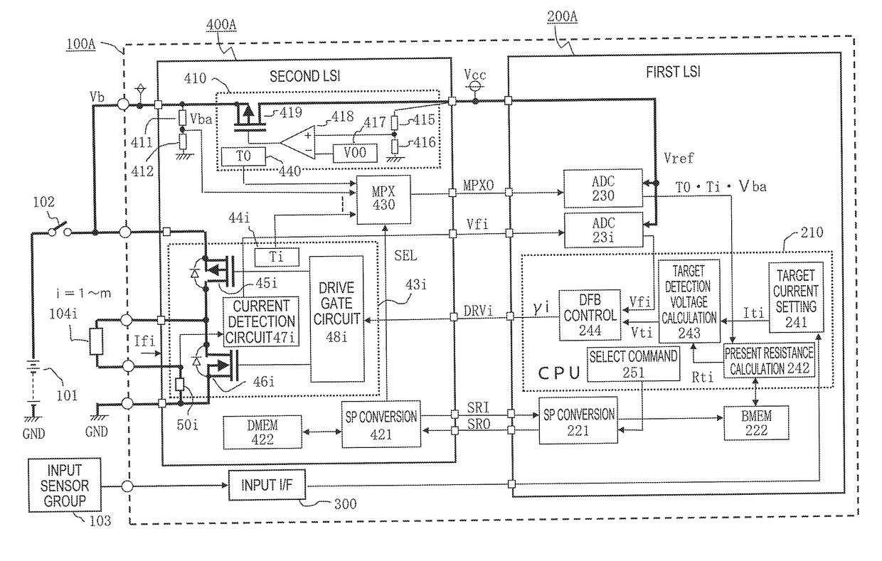
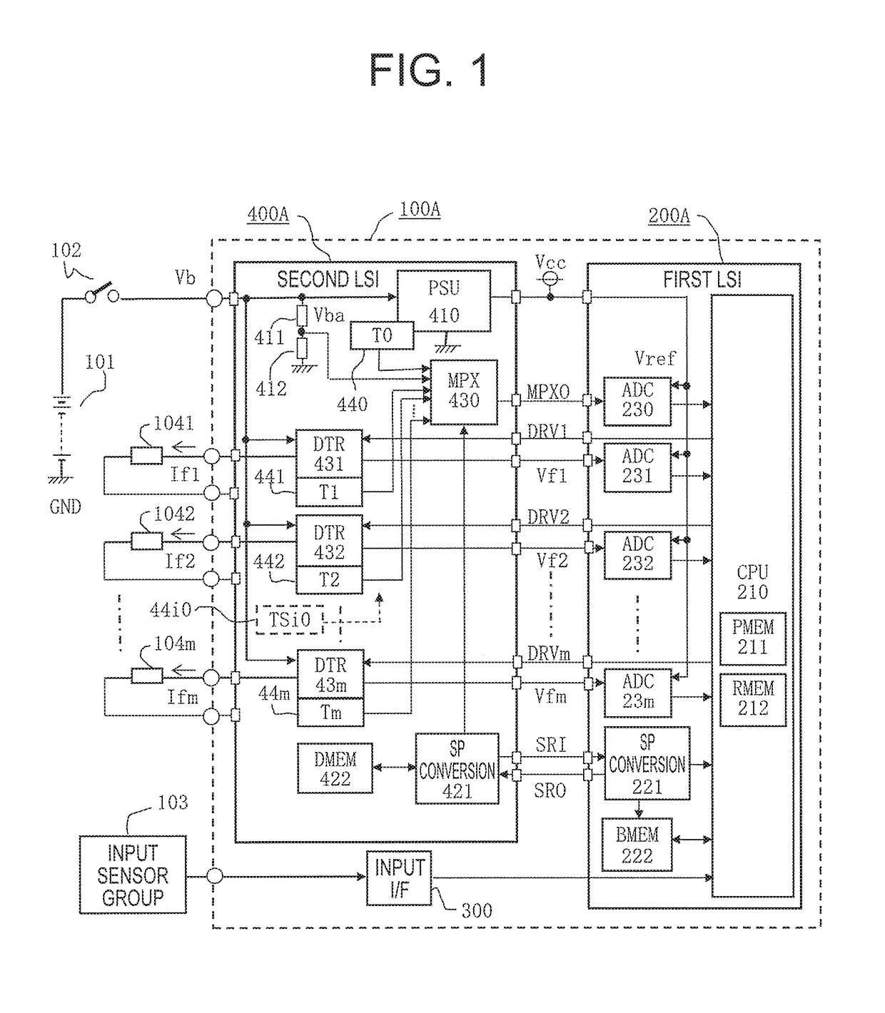
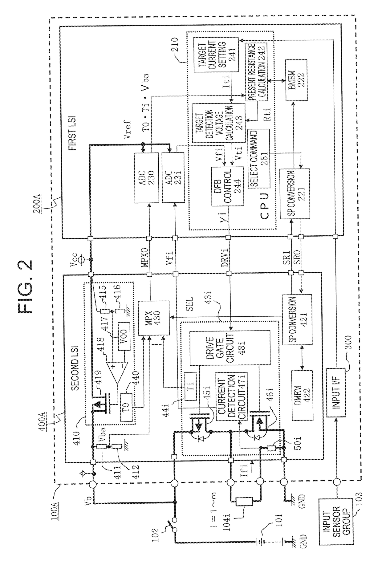
[0070]Configurations shown in FIG. 1, which is an overall circuit block diagram of a power supply control device according to a first embodiment of this invention, and FIG. 2, which is a detailed circuit block diagram relating to a power supply circuit portion of the power supply control device shown in FIG. 1, will be described in detail below.

[0071]First, in FIG. 1, a power supply control device 100A supplies a variable load current Ifi to each of a plurality of inductive loads 104i (i=1, 2, . . . m; likewise hereafter) that are formed from linear solenoids provided in a plurality of hydraulic solenoid valves used in an automobile transmission, for example, to select gear positions. The power supply control device 100A is configured such that a power supply voltage Vb is applied thereto from a DC power supply 101 serving as an in-vehicle battery via an output contact 102 of a power relay that is b...

second embodiment

Detailed Description of Second Embodiment

[0249](1) Detailed Description of the Configuration

[0250]Configurations shown in FIG. 7, which is an overall circuit block diagram of a power supply control device according to a second embodiment of this invention, and FIG. 8, which is a detailed circuit block diagram relating to one power supply circuit portion of the power supply control device shown in FIG. 7, will be described in detail below, focusing on differences with the configurations shown in FIGS. 1 and 2.

[0251]Note that the main difference is that in FIGS. 1 and 2, negative feedback control is executed on the load current Ifi by the microprocessor 210 provided in the first integrated circuit element 200A, whereas in FIGS. 7 and 8, control is implemented by a negative feedback control circuit 49i provided in a second integrated circuit element 400B. Accordingly, the microprocessor 210, which is provided in a first integrated circuit element 200B, generates the drive command signa...


PUM


Abstract

Correction coefficients corresponding to parameters by which characteristic variation is caused are stored in a data memory of a second integrated circuit element in which driving open/close elements respectively connected in series to a plurality of inductive loads are integrated, and a first integrated circuit element that cooperates with the second integrated circuit element suppresses a current control error accompanying individual variation among circuit components and environmental temperature variation by reading present values of the parameters and combining the present values with the correction coefficients. The correction coefficients are calculated by an adjustment tool in a state where the second integrated circuit element is provided singly, and therefore correction data can be generated in relation to a plurality of temperature environments easily.

Description

BACKGROUND OF THE INVENTION1. Field of the Invention[0001]This invention relates to improvements in a power supply control device that supplies individually variable load currents to a plurality of inductive loads, and in a correction data generation method applied to the power supply control device to correct variation in a control characteristic caused by temperature variation and individual variation among circuit components.2. Description of the Related Art[0002]In an automatic transmission for an automobile include, for example, three to six proportional solenoid valves are used to select a plurality of gear positions, and it is necessary to subject proportional solenoid coils (linear solenoids) of one or more thereof to simultaneous energization control using various target currents, and to implement high-precision current control adapted to the target currents on power supply open / close elements connected in series to the respective proportional solenoid coils by controlling ...

Claims


Application Information

Patent Timeline
IPC IPC(8): H02M1/08G05B15/02
CPCH02M1/08G05B15/02H02M2001/0009F16H2061/0255F16H61/0251G05F1/561H02M3/158F16H61/0006F16H2061/005H02M1/0006H02M1/0009H02M1/327
Inventor YANAI, TAKAYUKI
Owner MITSUBISHI ELECTRIC CORP
Why Eureka
Try Eureka