Communication system

a communication system and communication technology, applied in the field of communication systems, can solve the problems of rach involving collision risk and fear of insufficient radio resources all over the world, and achieve the effect of high throughput and high accuracy

Active Publication Date: 2018-05-03
MITSUBISHI ELECTRIC CORP
View PDF6 Cites 6 Cited by
  • Summary
  • Abstract
  • Description
  • Claims
  • Application Information

AI Technical Summary

Benefits of technology

[0073]The communication system according to the present invention is a communication system including a base station device and a communication terminal device. A signal is transmitted and received between the base station device and the communication terminal device through a multi-element antenna including a plurality of antenna elements. At least one of the base station device and the communication terminal device includes a calibration unit. The calibration unit performs calibration of phases and amplitudes of beams formed by the antenna elements when the signal is transmitted and received. The calibration unit obtains a correction value for the phases and the amplitudes of the beams in the respective a...

Problems solved by technology

The RACH involves a collision risk.
Widespread use of smartphones and tablet terminals explosively increas...

Method used


Image

  • Communication system
  • Communication system
  • Communication system

Examples


first embodiment

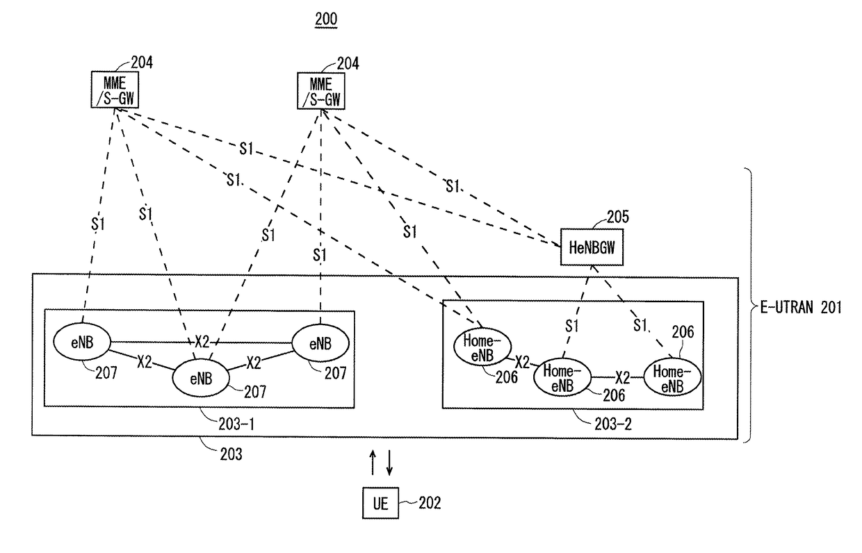
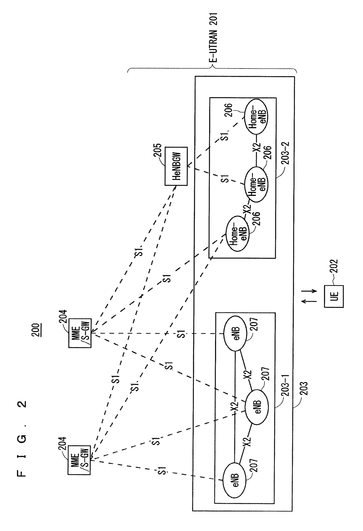
[0116]FIG. 2 is a block diagram showing an overall configuration of an LTE communication system 200, which is under discussion of 3GPP. FIG. 2 will be described. A radio access network is referred to as an evolved universal terrestrial radio access network (E-UTRAN) 201. A user equipment device (hereinafter, referred to as a “user equipment (UE)”) 202 that is a communication terminal device is capable of radio communication with a base station device (hereinafter, referred to as a “base station (E-UTRAN Node B: eNB)”) 203 and transmits and receives signals through radio communication.

[0117]Here, the “communication terminal device” covers not only a user equipment device such as a movable mobile phone terminal device, but also an unmovable device such as a sensor. In the following description, the “communication terminal device” may be simply referred to as a “communication terminal”.

[0118]The E-UTRAN is composed of one or a plurality of base stations 203, provided that a control pro...

second embodiment

[0251]The first embodiment describes a method for enabling improvement of a throughput by matching phase and amplitude differences among antenna elements included in a multi-element antenna. The second embodiment will disclose a method for solving a problem with requiring a long time to transmit the same number of cal-RSs when mapping of the cal-RSs for each of the antenna elements for calibration temporally varies.

[0252]This method is a method for arranging reference signals for calibration (cal-RSs) in the same subframe in an antenna element that transmits the cal-RSs.

[0253]FIG. 17 illustrates example mapping in transmission data of a first antenna element. FIG. 18 illustrates example mapping in transmission data of a second antenna element to an n-th antenna element. The horizontal axis represents a time t, and the vertical axis represents a frequency f in FIGS. 17 and 18. In FIGS. 17 and 18, a reference “1306” denotes a resource block.

[0254]In the example of FIG. 17, the first a...

third embodiment

[0273]The second embodiment describes a method for temporally localizing the mapping of cal-RSs for each antenna element that is required for calibration to enable shortening of the time required for calibration. However, the transmission sometimes overlaps with those of the other CHs or the other RSs, and the current standards do not cover such requirement. Thus, a non-avoidable problem with the requirement occurs. The third embodiment will disclose a method for solving the problem by providing a new mapping method.

[0274]FIG. 20 illustrates another example mapping in the transmission data of the first antenna element. FIG. 21 illustrates another example mapping in the transmission data of the second antenna element to the n-th antenna element. FIGS. 20 and 21 illustrate example mapping of downlink transmission bits for which a slot or a subframe for calibration or resource blocks 1504 and 1508 are provided.

[0275]As illustrated in FIG. 20, special mapping of not transmitting a part ...


PUM


Abstract

A signal is transmitted and received between a base station device and a communication terminal device that are included in a communication system, through a multi-element antenna including a plurality of antenna elements. At least one of the base station device and the communication terminal device includes a PHY processing unit that is a calibration unit that performs calibration of phases and amplitudes of beams formed by the antenna elements when the signal is transmitted and received. The PHY processing unit obtains a correction value for the phases and the amplitudes of the beams in the respective antenna elements so that the phases and the amplitudes of the beams are identical among the antenna elements, and performs the calibration based on the obtained correction value.

Description

TECHNICAL FIELD[0001]The present invention relates to a communication system in which radio communication is performed between a communication terminal device such as a user equipment device and a base station device.BACKGROUND ART[0002]The 3rd generation partnership project (3GPP), the standard organization regarding the mobile communication system, is studying communication systems referred to as long term evolution (LTE) regarding radio sections and system architecture evolution (SAE) regarding the overall system configuration including a core network and a radio access network, which will be hereinafter collectively referred to as a network as well (for example, see Non-Patent Documents 1 to 13). This communication system is also referred to as 3.9 generation (3.9 G) system.[0003]As the access scheme of the LTE, orthogonal frequency division multiplexing (OFDM) is used in a downlink direction and single carrier frequency division multiple access (SC-FDMA) is used in an uplink di...

Claims


Application Information

Patent Timeline
IPC IPC(8): H04B17/12H04W72/04H04B7/06H01Q3/26
CPCH04B17/12H04W72/042H04B7/0634H01Q3/2605H04B7/0842H04B7/0617H01Q3/267H04B7/0413H04B7/10H04L5/0023H04L5/0048H04W16/28H04W72/04H04W72/23
Inventor MORISHIGE, HIDEKINAKAZAWA, MASAYUKIMOCHIZUKI, MITSURUHARA, YOSHITAKASUZUKI, KUNIYUKI
Owner MITSUBISHI ELECTRIC CORP
Why Eureka
Try Eureka