Compact platen roller motion system for thermal printing mechanism

a motion system and thermal printing technology, applied in printing, other printing apparatus, etc., can solve problems such as heat dissipation problems, and achieve the effects of simplifying motion means, reducing the number of parts, and reducing the global volume of a small thermal printing mechanism

Inactive Publication Date: 2018-05-10
APS TRADING OOD
View PDF2 Cites 1 Cited by
  • Summary
  • Abstract
  • Description
  • Claims
  • Application Information

AI Technical Summary

Benefits of technology

[0007]The aim of the present invention is to reduce the global volume of a small thermal printing mechanism by simplifying the motion means, reducing the number of parts and simplifying its construction while o

Problems solved by technology

In the cases where small diameter stepper motor is used, usually 10 mm, the heat dissipation becomes problematic, and so

Method used


Image

  • Compact platen roller motion system for thermal printing mechanism
  • Compact platen roller motion system for thermal printing mechanism
  • Compact platen roller motion system for thermal printing mechanism

Examples


Embodiment Construction

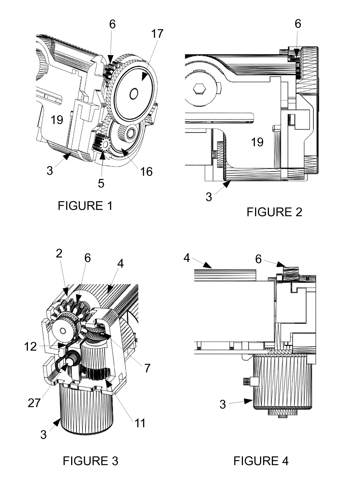
[0046]Thermal printer mechanism according to present invention comprises a printer chassis 1, a thermal printhead 2 fixedly mounted on the printer chassis, a platen roller 4 with a platen roller shaft 9, on which a platen roller gear 6 is fixedly mounted, and a platen roller motion unit that comprises a motor 3 for rotating the platen roller 4 through a gear train that engages said platen roller gear 6.

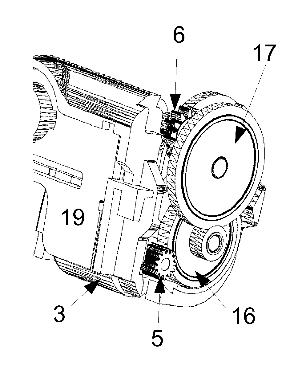
[0047]FIG. 1 shows a prior art arrangement of the platen roller motion unit where the motor 3 for rotating of the platen roller is in a vertical motor variant, i.e. the motor gear axis is substantially parallel to the platen roller shaft and is positioned below the thermal printhead. A motor spur gear 5 is driving a set of vertical spur gears 16 and 17 called a gearbox. Gear 17 drives the platen roller 4 through the gear 6 which is mounted to it. Finally, the motor is mounted on a metallic flange 19 to increase its heat dissipation.

[0048]As shown on FIG. 2, which is a back view of the...


PUM


Abstract

Thermal printing mechanism having a printer chassis, a thermal printhead, a motor for rotating a platen roller with a motor spur gear, a platen roller with a platen roller gear mounted on it, the platen roller gear being a worm wheel able to engage with a worm screw. The motor is mounted so that its gear axis is substantially parallel to the thermal printhead surface which is in contact with the platen roller, and perpendicular to the platen roller shaft. The thermal printing mechanism additionally includes a gear shaft mounted substantially parallel to the motor gear axis, the gear shaft having at one end a spur gear able to engage with the motor spur gear, and at the other end a worm screw, able to engage with the platen roller gear.

Description

TECHNICAL FIELD OF THE INVENTION[0001]The present invention is in the field of the thermal printing mechanisms. Such printers are widely used in handheld payment terminals where compactness and cost are the main factors of improvements.PRIOR ART[0002]A thermal printing mechanism usually comprises a chassis for holding all of the following components: a thermal printhead, a platen roller that can be put in rotation by a motor trough a gear train, and pushing means in order to keep under pressure the thermal printhead against the platen roller. A thermal sensitive paper is inserted between the platen roller and the thermal printhead, and the printout is generated by combining the paper advance with the dot selection and activation on the thermal printhead.[0003]An improvement of such device is providing the possibility to separate the platen roller from the thermal printhead and the chassis in order to facilitate the loading of the paper and its positioning between the thermal printhe...

Claims


Application Information

Patent Timeline
IPC IPC(8): B41J2/32B41J11/04B41J23/02
CPCB41J2/32B41J11/04B41J23/02B41J2/315
Inventor MONTAGUTELLI, DENIS
Owner APS TRADING OOD
Why Eureka
Try Eureka