
Two-stroke internal combustion engine

Inactive Publication Date: 2018-05-10
MERCIER CESAR
View PDF4 Cites 0 Cited by
  • Summary
  • Abstract
  • Description
  • Claims
  • Application Information

AI Technical Summary

Benefits of technology

The invention is a new engine design that uses a unique cam and follower configuration to transfer force safely to the piston for a long time. This design uses both action and reaction forces, resulting in more power output with no recoil. The engine also uses hydraulics to distribute forces in all directions and prevents shaking of the engine mounts. The engine features a shape charged combustion chamber and is designed for load balancing, redundancy, and fault tolerance. An optional configuration allows for easy installation and maintenance.

Problems solved by technology

This setup causes energy to be wasted in form of heat and NOx while the piston is near top dead center.
However, conventional cam and follower engine designs have not been successful due to in part problems related to roller bearing followers whereas the force of the piston is applied on the cam using a small contact point on the roller bearing and cam surface.

Method used


Image

  • Two-stroke internal combustion engine
  • Two-stroke internal combustion engine
  • Two-stroke internal combustion engine

Examples


Embodiment Construction

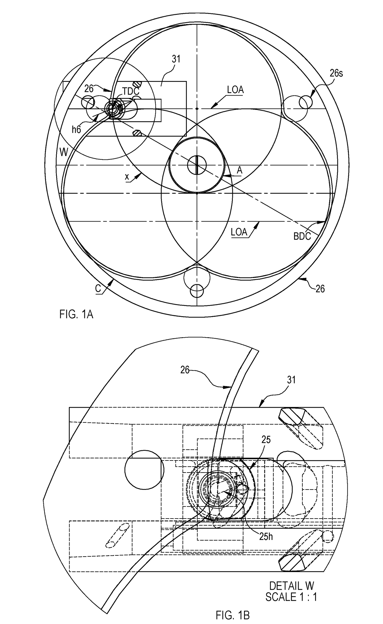
[0110]A preferred method or setup for translating reciprocating motion into rotary motion using a cam and follower mechanism to achieve maximum torque and power per size ratio will now be described. The cam profile 26 of FIG. 1A is made of a plurality of intersecting circles X, that are curved at their intersections to form a smooth endless groove or of peaks and valleys cam profile. The Line Of Action (LOA) perpendicularly intersects the cam profile near Top Dead Center (TDC), to efficiently translate the combustion force into rotary motion. The center circle A is tangent to the intersecting circles X. The diameter of circle X is about 3 times the diameter of circle A, which is about the dimension of the moment arm length. Near Bottom Dead Center (BDC) the circle C intersects the X circles. A basic formula can be used as follows: X=A x 3. Using this three circle cam profile, we are able to have one follower 25 pushing on a cam 26 near top dead center TDC, while another follower pus...


PUM


Abstract

A cam and follower apparatus adapted to translate the force of a piston to turn the shaft of an engine. The cam profile is made of three intersecting circles allowing for one follower to be near top dead center while another follower is near bottom dead center. The surface of the follower is a circle which shares the same center point and radius with the circles of the cam profile. The surface of the follower also closely intersects the axis of the follower preventing the follower from spinning like a roller follower. The follower can therefore spread the force from the piston to a wider area on the cam for longevity.

Description

[0001]This invention relates generally to the method or an apparatus for converting linear motion into rotational motion using cams and followers, suitable for use in a rotary engine. This invention relates to a balanced engine that uses a special Cam and Follower configuration to achieve maximum torque and durability. This engine also relates to a float-less valve and cam configuration that can be screwed to an internal combustion engine.BACKGROUND OF THE INVENTION[0002]Engineers have been trying to find efficient ways to convert reciprocal motion into rotary motion ever since the creation of the first internal combustion engine. Such a solution will help to design a new engine that can consume petroleum fuel more efficiently. My new engine will allow manufacturers to build new engines that are smaller, lighter, more efficient, powerful and durable.BRIEF SUMMARY OF THE INVENTION[0003]This engine operates similarly to a conventional two-cycle engine, but the similarity stops there. ...

Claims


Application Information

Patent Timeline
IPC IPC(8): F01L1/18F02B75/02F02B75/30F01L1/46
CPCF01L1/18F02B75/02F02B75/30F01L1/462F02B2075/025F01L1/04F01L1/38F01L1/40F01L21/02F01B2009/061F01B7/20F02B75/32
Inventor MERCIER, CESAR
Owner MERCIER CESAR
Features
  • Generate Ideas
  • Intellectual Property
  • Life Sciences
  • Materials
  • Tech Scout
  • Unparalleled Data Quality
  • Higher Quality Content
  • 60% Fewer Hallucinations
Learn More