
Complex energy system in bidirectional energy network and control method thereof

a technology of energy network and complex energy system, applied in the direction of electric variable regulation, process and machine control, instruments, etc., can solve the problems of unidirectional energy management, energy technology, especially power supply, and difficulty in energy technology

Active Publication Date: 2018-05-10
KOREA INST OF ENERGY RES
View PDF2 Cites 2 Cited by
  • Summary
  • Abstract
  • Description
  • Claims
  • Application Information

AI Technical Summary

Benefits of technology

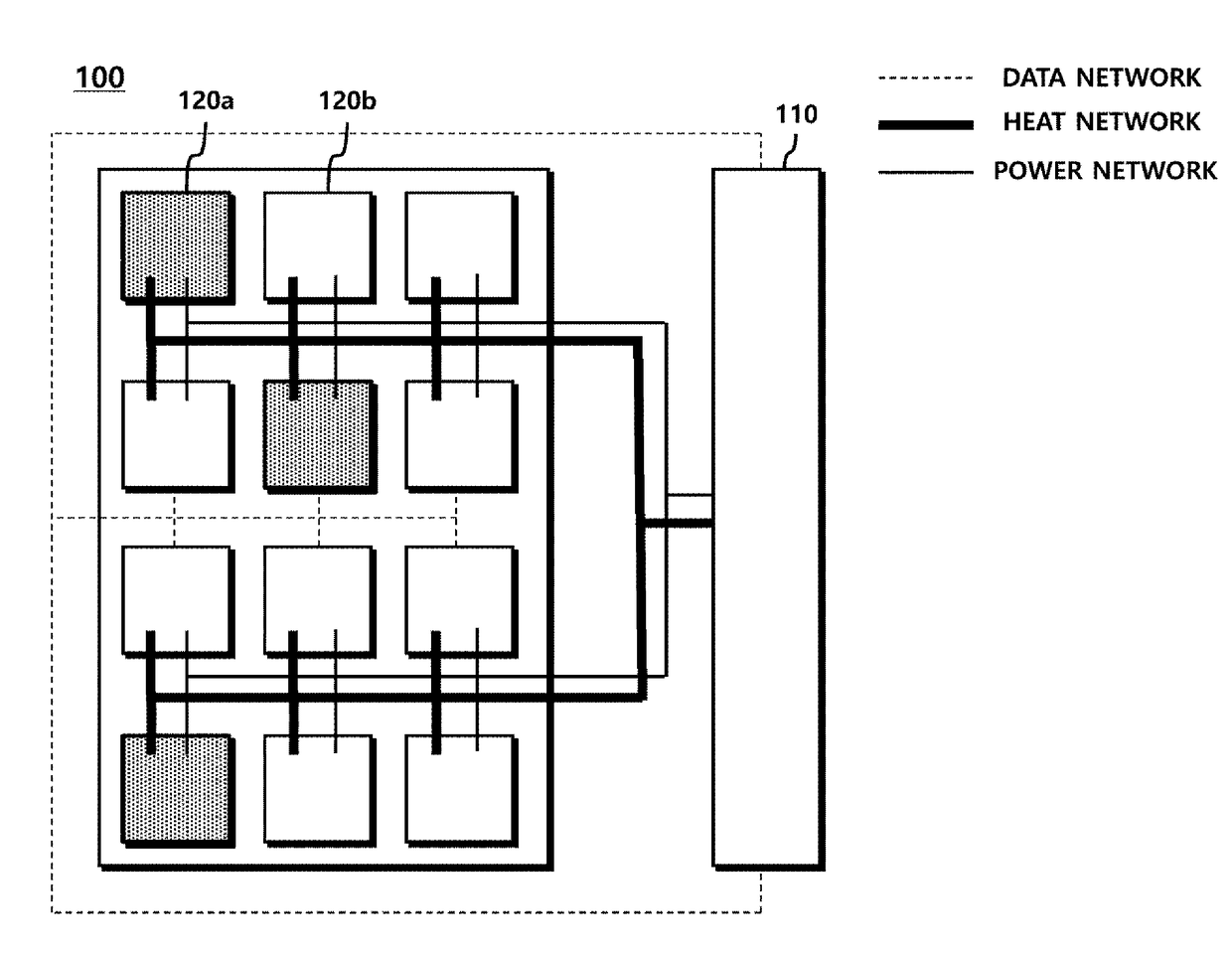
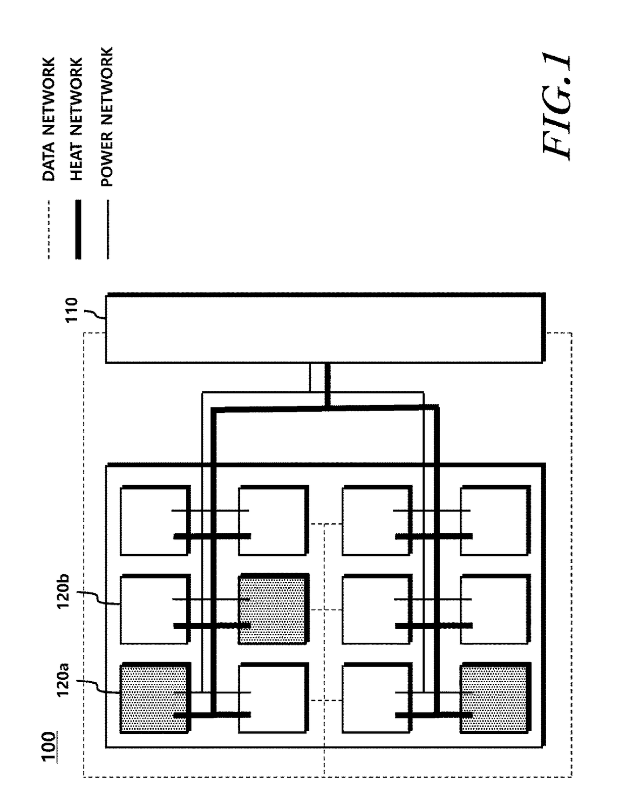
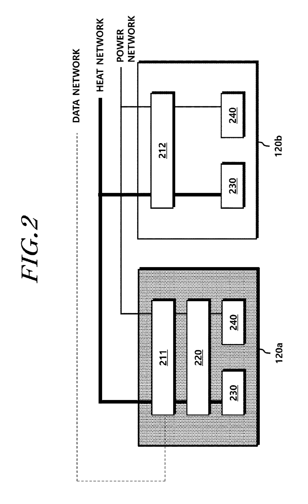
The present invention relates to a control method for a complex energy system that supplies heat and power to energy consumers through a heat network and a power network. The method involves monitoring energy consumption information of the energy consumers, confirming an energy price applied to each of the energy consumers, calculating the total energy consumption cost of the energy consumers, and controlling a cogenerator and a heat generator so that the sum of the power supply amount of the cogenerator, the power consumption amount of the energy consumers, the heat supply amount of the cogenerator, the heat supply amount of the heat generator, and the target function value obtained by subtracting the total energy consumption cost from the sum of the power consumption cost and the external power grid is maximized. The invention allows for a more efficient use of energy and cost savings for energy suppliers and consumers.

Problems solved by technology

In recent years, energy technology—especially, a technology for large power generation and central supply in terms of power supply—has difficulties due to environmental problems and residents' opposition to establishment of power plants and power transmission and transformation facilities.
However, such a system independently manages and controls electricity and heat and also performs unidirectional energy management such that energy flows only in a direction from a supplier side to a consumer side.
Thus, the management cannot be performed on bidirectional energy network systems.
However, the existing cogeneration systems allow only a unidirectional transaction, that is, can just supply heat and power to customers and do not allow a bidirectional transaction of energy with customers that hold energy sources.

Method used


Image

  • Complex energy system in bidirectional energy network and control method thereof
  • Complex energy system in bidirectional energy network and control method thereof
  • Complex energy system in bidirectional energy network and control method thereof

Examples


Embodiment Construction

[0027]Hereinafter, embodiments of the present invention will be described in detail with reference to the accompanying drawings. In adding reference numerals for elements in each figure, it should be noted that like reference numerals are used to denote like elements in other figures wherever possible. Moreover, detailed descriptions related to well-known functions or configurations will be omitted so as not to unnecessarily obscure the subject matter of the present invention.

[0028]In addition, terms such as first, second, A, B, (a), (b) or the like may be used herein when describing elements of the present invention. These terms are merely used to distinguish one structural element from other structural elements, and a property, an order, a sequence and the like of a corresponding structural element are not limited by the term. It should be noted that if it is described in the specification that one element is “connected,”“combined” or “coupled” to another element, a third element ...


PUM


Abstract

Provided is a control method of a complex energy system that supplies heat and power to energy consumers through a heat network and a power network. The control method includes monitoring energy consumption information of the energy consumers and confirming an energy price applied to each of the energy consumers, calculating a total energy consumption cost of the energy consumers according to the energy price and the energy consumption information, and controlling a cogenerator and a heat generator so that a sum of a power supply amount of the cogenerator and a power consumption amount from an external power grid is equal to a total power consumption amount of the energy consumers, a sum of a heat supply amount of the cogenerator and a heat supply amount of the heat generator is equal to a total heat consumption amount of the energy consumers, and a target function value obtained by subtracting the total energy consumption cost from a sum of a power consumption cost from the external power grid and operating costs of the cogenerator and the heat generator is maximized.

Description

CROSS-REFERENCE TO RELATED APPLICATIONS[0001]This application claims priority from Korean Patent Application No. 10-2016-0147805 filed on Nov. 8, 2016, which is hereby incorporated by reference for all purposes as if fully set forth herein.BACKGROUND OF THE INVENTIONField of the Invention[0002]The present invention relates to energy management technology, and more particularly, to a technology for integrated management of heat and power.Description of the Related Art[0003]In recent years, energy technology—especially, a technology for large power generation and central supply in terms of power supply—has difficulties due to environmental problems and residents' opposition to establishment of power plants and power transmission and transformation facilities. Accordingly, the paradigm of energy supply has been changed to distributed power generation. Furthermore, most countries including South Korea are increasing the proportion in which new renewable energy sources such as solar powe...

Claims


Application Information

Patent Timeline
IPC IPC(8): G06Q50/06G05F1/66G06Q30/02G06Q10/06
CPCG06Q50/06G06Q10/06313G06Q30/0283G05F1/66Y04S50/14Y02P90/82G01R11/32G06Q20/14Y02E20/14
Inventor HAN, SOO BINOH, SEASEUNGCHAE, SU YONGCHOI, JAEJOON
Owner KOREA INST OF ENERGY RES
Learn More