Semiconductor substrate structures, semiconductor devices and methods for forming the same

Active Publication Date: 2018-05-10
VANGUARD INTERNATIONAL SEMICONDUCTOR CORPORATION
View PDF3 Cites 7 Cited by
  • Summary
  • Abstract
  • Description
  • Claims
  • Application Information

AI Technical Summary

Benefits of technology

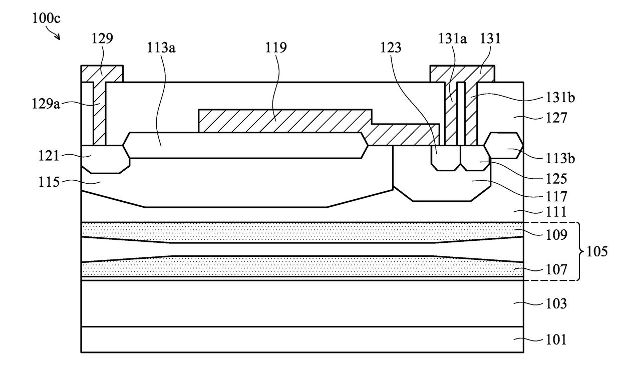
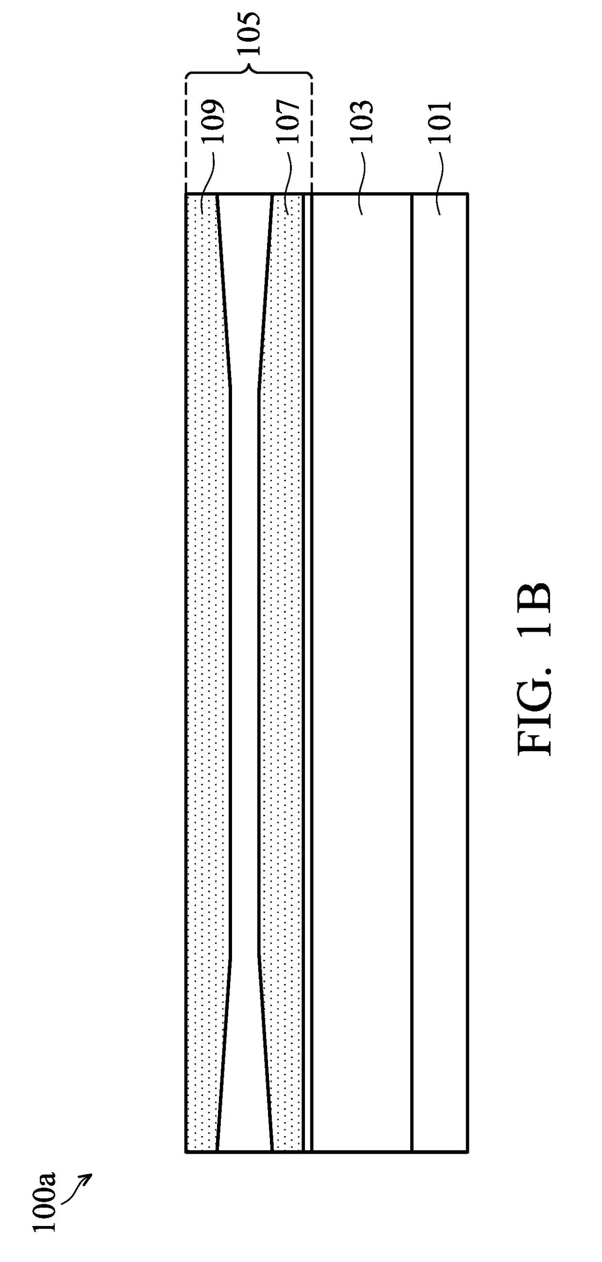
[0005]Embodiments of semiconductor substrate structures of semiconductor devices and methods for forming the same are provided. The backside bias effect, which changes the breakdown voltages of the metal-oxide-semiconductor field-effect transistors, is one of the main problems of semiconductor devices with silicon-on-insulator substrates. To overcome the aforementioned problems, an n-type buried layer and a p-type buried layer are implanted in the silicon-on-insulator substrates, which can eliminate the backside bias effect without using additional masks for forming additional circuitries for the device in the overall process.

Problems solved by technology

The backside bias effect, which changes the breakdown voltages of the metal-oxide-semiconductor field-effect transistors, is one of the main problems of semiconductor devices with silicon-on-insulator substrates.

Method used


Image

  • Semiconductor substrate structures, semiconductor devices and methods for forming the same
  • Semiconductor substrate structures, semiconductor devices and methods for forming the same
  • Semiconductor substrate structures, semiconductor devices and methods for forming the same

Examples


Embodiment Construction

[0014]The following disclosure provides many different embodiments, or examples, for implementing different features of the subject matter provided. Specific examples of components and arrangements are described below to simplify the present disclosure. These are, of course, merely examples and are not intended to be limiting. For example, the formation of a first component over or on a second component in the description that follows may include embodiments in which the first and second components are formed in direct contact, and may also include embodiments in which additional components may be formed between the first and second components, such that the first and second components may not be in direct contact. In addition, the present disclosure may repeat reference numerals and / or letters in the various examples. This repetition is for the purpose of simplicity and clarity and does not in itself dictate a relationship between the various embodiments and / or configurations discu...


PUM


Abstract

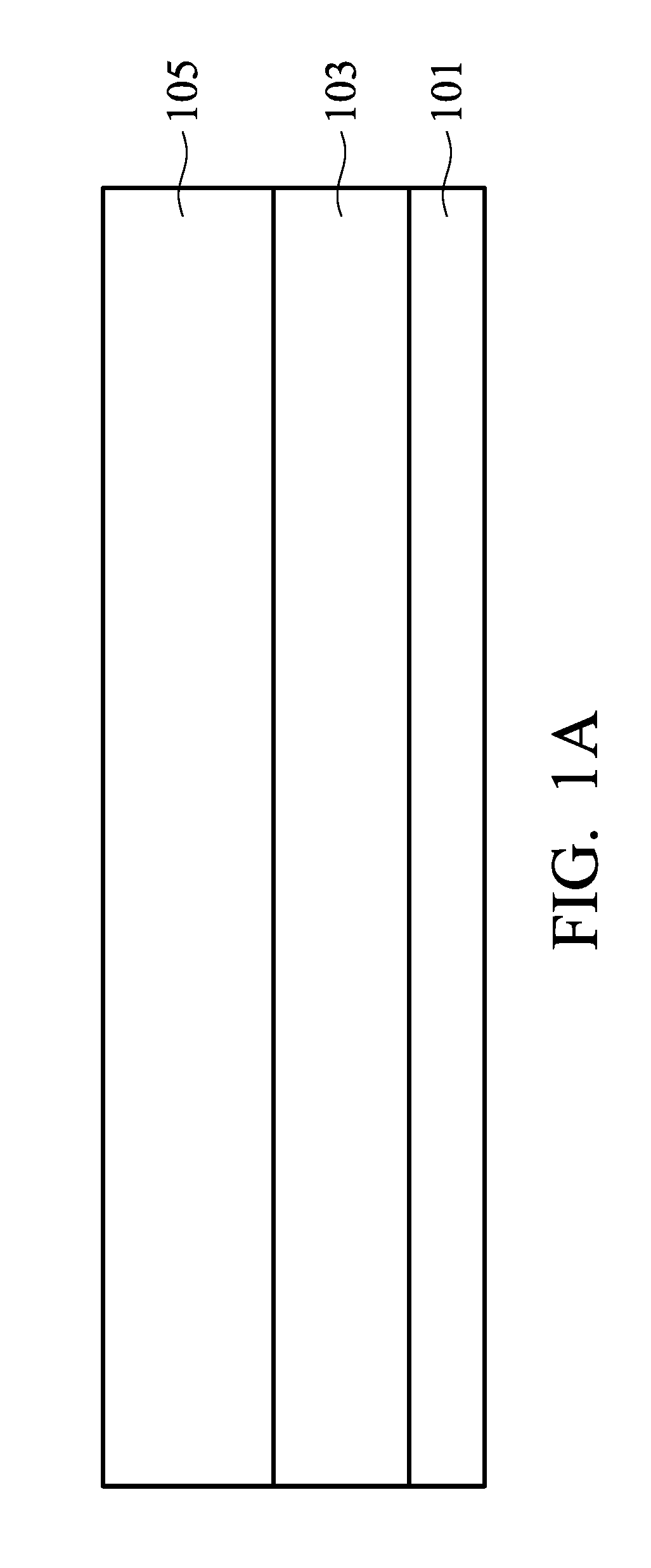
A semiconductor substrate structure includes a substrate having a first conductivity type, an oxide layer disposed on the substrate, and a semiconductor layer disposed on the oxide layer. The semiconductor substrate structure also includes a first buried layer disposed in the semiconductor layer, having a second conductivity type opposite to the first conductivity type. The semiconductor substrate structure further includes a second buried layer disposed in the semiconductor layer and above the first buried layer, having the first conductivity type, wherein the first buried layer and the second buried layer are separated by a distance.

Description

BACKGROUND OF THE INVENTIONField of the Invention[0001]The invention relates to semiconductor devices, and in particular to semiconductor substrate structures of semiconductor devices and methods for forming the same.Description of the Related Art[0002]In the semiconductor industry, silicon-on-insulator (SOI) is a silicon-insulator-silicon substrate which can replace conventional silicon substrates. This involves a buried oxide layer sandwiched between the base silicon and the top silicon. The advantages of silicon-on-insulator technology relative to conventional bulk silicon substrates include lower leakage current, higher power efficiency, lower parasitic capacitance, and resistance to latch-up.[0003]However, in general, silicon-on-insulator devices suffer from the backside bias effect, which is also called the substrate bias effect. The backside bias effect occurs when the breakdown voltage of a metal-oxide-semiconductor field-effect transistor (MOSFET) is affected by the voltage...

Claims


Application Information

Patent Timeline
Patent Type & Authority Applications(United States)
IPC IPC(8): H01L29/78H01L29/06H01L29/36H01L21/265H01L21/762
CPCH01L29/7835H01L29/0649H01L21/76243H01L21/265H01L29/36H01L21/76202H01L29/42368H01L29/7816H01L29/0878H01L29/1083
Inventor HUNG, PEI-HENGKUMAR, MANOJLEE, CHIA-HAO
Owner VANGUARD INTERNATIONAL SEMICONDUCTOR CORPORATION
Why Eureka
Try Eureka