Body-wearable antenna system

a technology of bodywearing and antenna system, which is applied in the direction of antenna details, antenna adaptation in movable bodies, antennas, etc., can solve the problems of omnidirectional antennas, by their very nature, exhibit finite and lower gain values than can be achieved using directional antennas, and achieve the effect of reducing the size, weight and power of any equipment supplying the antenna system, reducing the input power required by the transmitting antenna, and increasing the gain

Inactive Publication Date: 2018-05-10
THE SEC OF STATE FOR DEFENCE IN HER BRITANNIC MAJESTYS GOVERNMENT OF THE UK OF GREAT BRITAIN & NORTHERN IRELAND
View PDF6 Cites 2 Cited by
  • Summary
  • Abstract
  • Description
  • Claims
  • Application Information

AI Technical Summary

Benefits of technology

[0009]Use of a plurality of directional antenna elements that are substantially equi-spaced) around the user's body and operated in-phase with each other can deliver a combined omnidirectional performance that provides an improved power delivery mechanism, providing higher gain performance than one or more conventional body-worn omnidirectional antennas., The gain of the antenna system is increased simply by migrating to a suitably designed directional antenna element strategy, wherein each antenna element has a radiation pattern such that, when all antenna elements in the antenna system are combined and operated in-phase with each other, provides the overall omnidirectional performance of the antenna system. A person skilled in the art will realise that for directional antenna elements as the desired frequency of operation is changed, the respective radiation pattern may also change. The beam-width for a particular antenna element may be narrower at certain frequencies than at others, thereby requiring more of said directional antenna elements to achieve omnidirectional coverage. When two directional antenna elements, with appropriate respective radiation patterns, are equally distributed around a user's body, the radiated power is directed away from the body allowing stronger concentrations of power to be formed substantially all around the user, when compared to using one or more omnidirectional antenna elements, thereby minimising shadowing effects. If only two antenna elements are used it will be understood that an appropriate antenna element radiation pattern cannot be overly directional, since power will need to be radiated in all directions from around the user's body. Alternatively a distributed array comprising more than two directional antenna elements may be used.
[0033]For example, the antenna system may be configured to provide a diversity capability for use in the communications field to exploit the multipath behaviour in non-line of sight environments. As the antenna elements are designed and configured to point their main beams in different spatial directions, this antenna system can be used to provide ‘angle or pattern diversity’ which can be employed to increase data rates and combat any multipath fading that arises in the propagation channel. To achieve this, a comparator stage can be integrated into the receiver equipment and the provision of a signal processor allows for signal processing algorithms to be performed to enact the desired diversity scheme (i.e. selection combining, equal gain combining, maximal ratio combining etc.).

Problems solved by technology

When omnidirectional antenna elements are mounted on a user's body, some power will be absorbed and dissipated by the body, causing shadowing effects or drops in radiated power in certain directions.
However, omnidirectional antennas, by their very nature, exhibit finite and lower gain values than can be achieved using directional antennas.

Method used


Image

  • Body-wearable antenna system
  • Body-wearable antenna system
  • Body-wearable antenna system

Examples


Embodiment Construction

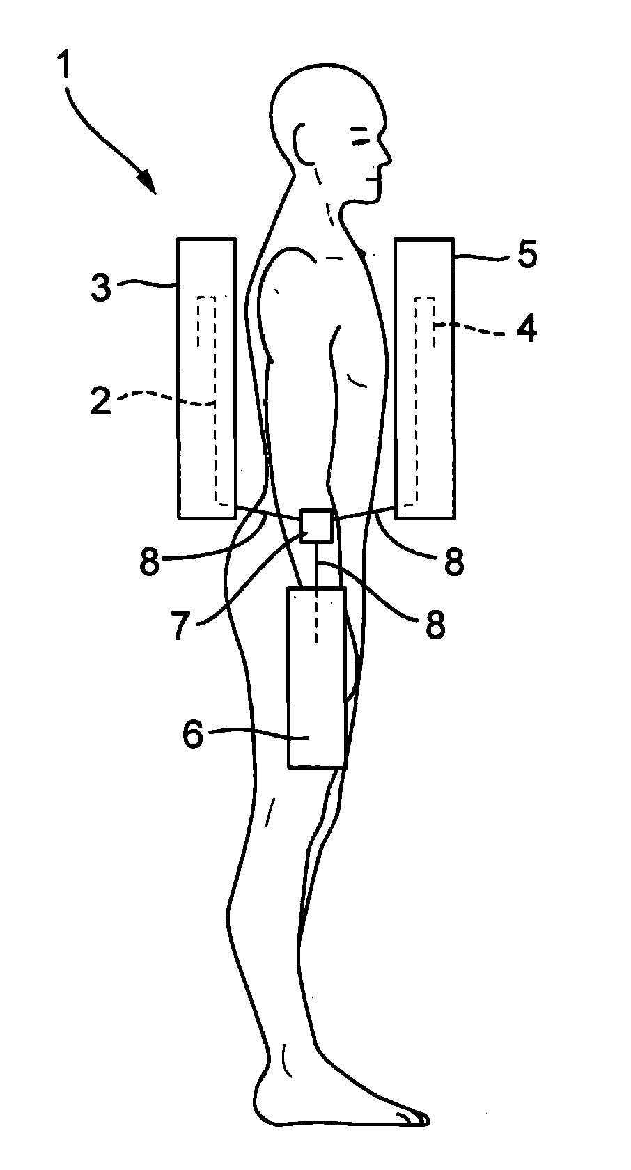
[0045]FIG. 1 shows, in schematic form, a person wearing an antenna system 1 in accordance with an embodiment of the invention. A first antenna element 2 is securely mounted within a first radome 3 and worn on the back of the user. A second antenna element 4 is mounted within a second radome 5 and worn on the front of the user. In this embodiment the antenna elements are in the form of PIFA. The radomes 3, 5 are made from a suitable hard plastics material, which is transparent to electromagnetic waves, in order to protect the antenna elements from damage during use. A series of mounting pillars is formed inside the radome to provide an elevated “pillar” that is drilled and tapped to suit an appropriate nylon screw, which is used to secure the PIFA firmly in position. Each antenna element 2, 4 is connected via a connector (not shown) to a coaxial cable 8 which electrically connects the antenna elements to a 2:1 zero degree phase power divider 7. A further coaxial cable 8 connects the ...


PUM


Abstract

A body-wearable antenna system is described that comprises at least two antenna elements (2, 4) arranged to be mountable in a substantially equi-spaced distributed array around a user's body. Each antenna element is a directional type antenna and the antenna system is configurable such that when worn the antenna elements operate in phase to deliver a combined, higher gain, omnidirectional performance radiating away from the user's body, compared to one or more conventional body-worn omnidirectional antennas. The antenna system can operate in transmit and receive. Each antenna element may be a planar inverted-F antenna (PIFA) housed in a protective radome (3, 5). Each PIFA may feature at least one slot cut into the radiating top plate or at least one parasitic radiator, or a combination of both, to allow operation within distinct frequency bands and with predetermined impedance bandwidth.

Description

TECHNICAL FIELD OF THE INVENTION[0001]This invention relates to a body-wearable antenna system, and particularly to a body-wearable antenna system capable of providing improved radiation efficiency in an omnidirectional Manner.BACKGROUND TO THE INVENTION[0002]Body-wearable antennas are now well known for transmitting and receiving signals for various Radio Frequency (RF) applications including communications. The primary advantage being that the user can remain essentially “hands-free” and maintain a high degree of freedom of movement. For certain applications, particularly, but not exclusively, applicable to search and rescue, security and military services, it is necessary to provide omnidirectional performance in both transmit and receive mode. This can be achieved using conventional monopole, dipole and planar type structures.[0003]For example US 2004 / 0004573 (Apostolos) describes a direction finding system using body-worn antennas, wherein the direction of a source of electroma...

Claims


Application Information

Patent Timeline
Patent Type & Authority Applications(United States)
IPC IPC(8): H01Q1/27H01Q3/34H01Q21/06
CPCH01Q1/273H01Q3/34H01Q21/062H01Q21/067
Inventor BOYES, STEPHEN JOHN
Owner THE SEC OF STATE FOR DEFENCE IN HER BRITANNIC MAJESTYS GOVERNMENT OF THE UK OF GREAT BRITAIN & NORTHERN IRELAND
Why Eureka
Try Eureka