
Intelligent docking system with automated stowage for uavs

a docking system and intelligent technology, applied in the direction of photovoltaic supports, launch/towing gear, transportation and packaging, etc., can solve the problems of deteriorating the reliability and safe operation of the aircraft, prior art systems, and generally complex and complicated setups that are expensive, and do not provide adequate safety and protection. , to achieve the effect of simple effective and economical operation

Inactive Publication Date: 2018-05-17
POH CHUNG KIAK +1
View PDF2 Cites 9 Cited by
  • Summary
  • Abstract
  • Description
  • Claims
  • Application Information

AI Technical Summary

Benefits of technology

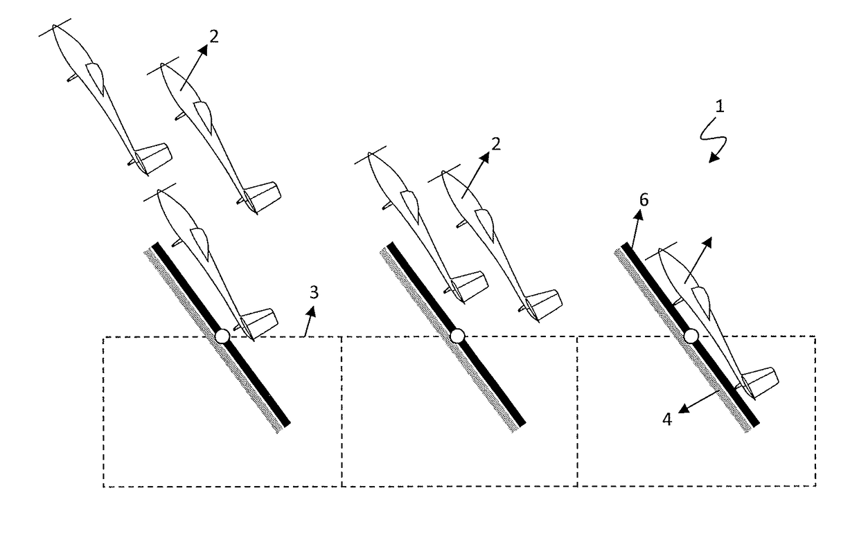
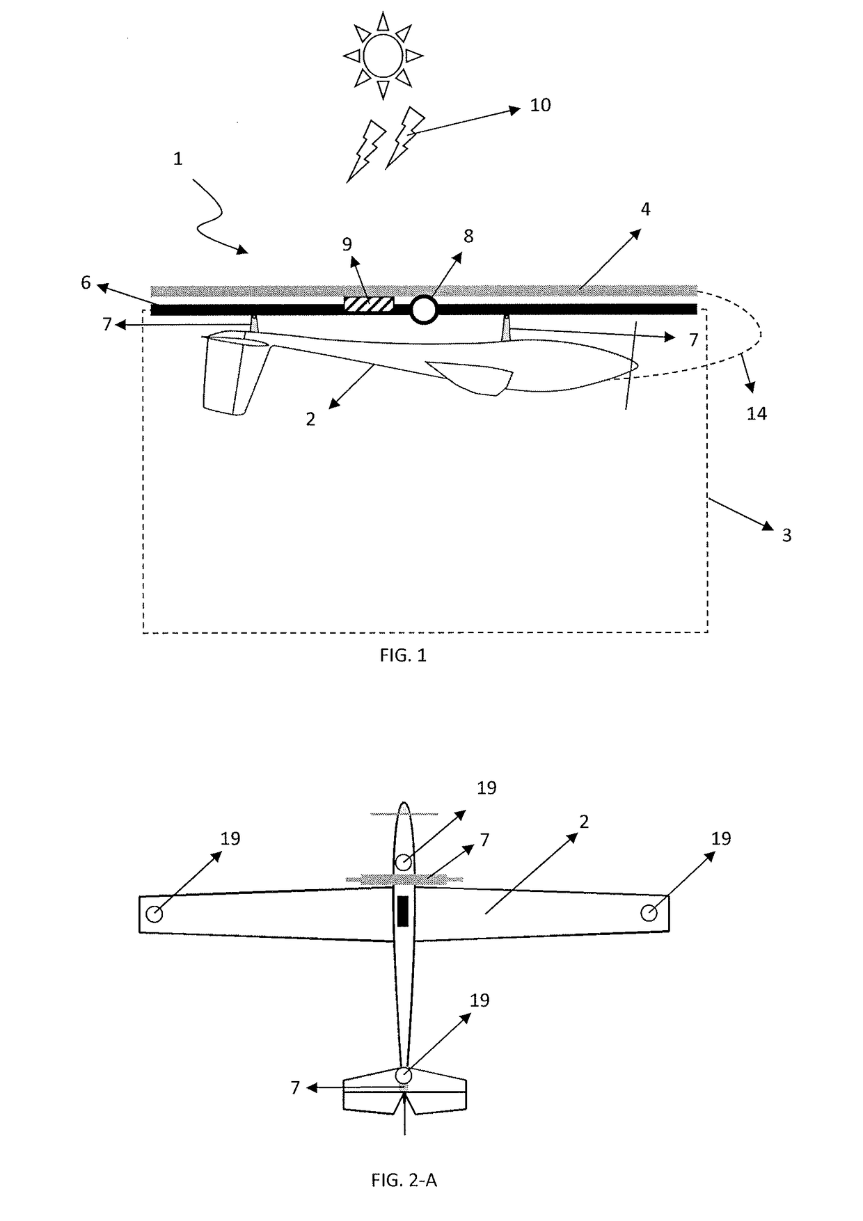
The present invention provides a fully automated docking system for fixed and non-fixed wing unmanned vehicles with the ability to dock, stow, replenish energy, and re-launch without human intervention. This system can handle fixed wing UAVs that can perform "Harrier" maneuver and VTOL (vertical take-off and landing) maneuver. The system includes an opened top compartment that can safely stow both fixed and non-fixed wing UAVs away from weather elements such as gusty winds, rain-water, and damaging ultraviolet exposure. The system is simple and economical to operate and manufacture.

Problems solved by technology

However, a key disadvantage of fixed-wing aircraft is that they generally require a runway for taking off and landing with an airspeed of approximately 30 kmh−1 and above depending on the wing loading.
However, present day solutions often involve significant increase in mechanical complexity of the aircraft which in turn deteriorate the reliability and safe operation of the aircraft.
Prior art systems, so far, are generally complex and complicating setups that are expensive and do not provide adequate safety and protection to the UAVs against structural damage as well as against harsh weather elements and conditions.
Prior arts generally cater for docking and launching of UAVs under good weather conditions and, so they are not expected to operate well under wet and gusty conditions or with satisfactory long-term operational reliability needed for remote region applications.

Method used


Image

  • Intelligent docking system with automated stowage for uavs
  • Intelligent docking system with automated stowage for uavs
  • Intelligent docking system with automated stowage for uavs

Examples


Embodiment Construction

[0046]In the following detailed description, numerous specific details are set forth in order to provide a thorough understanding of the invention. However, it will be understood by the person having ordinary skill in the art that the invention may be practised without these specific details. In other instances, well known methods, procedures and / or components have not been described in detail so as not to obscure the invention.

[0047]The invention will be more clearly understood from the following description of the embodiments thereof, given by way of example only with reference to the accompanying drawings, which are not drawn to scale.

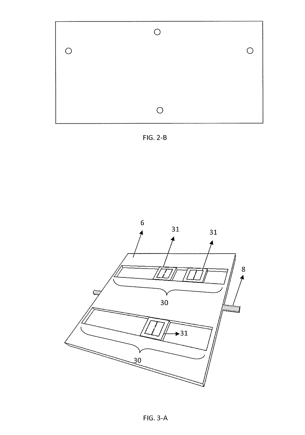
[0048]Referring to FIG. 1 illustrates side view of the present invention of docking system (1) for fixed or non-fixed wing unmanned aerial vehicles (2), comprising at least one docking and launching surface (6) to enable a vehicle (2) to dock and launch, and at least one energy harvesting surface (4) is disposed opposite of the surface (6), preferab...


PUM


Abstract

The present invention generally relates to a system and method of a docking system (1) for fixed wing unmanned aerial vehicle, or non-fixed wing unmanned aerial vehicle (2) such as rotorcraft, or combination thereof, comprising at least a docking and / or launching pad capable of being arranged in an array or staggered manner; said pad has a surface (6) for said vehicle docking and launching, said docking and launching surface (6) comprising moveable pads (31) which include electromagnets that can be energized to capture a docking vehicle (2); and another energy harvesting surface (4) has photovoltaic panel to harness solar energy to generate electricity or hydrogen fuel for a variety of on-board applications such as to charge said vehicle (2) and to power the docking system and providing a safe stowage and protected storage for the said vehicle (2).

Description

1. TECHNICAL FIELD OF THE INVENTION[0001]The present invention generally relates to a system and method of a docking system for unmanned aerial vehicles (UAVs) and in particular it relates to an autonomous docking and relaunching system that caters for vertical take-off and landing (VTOL) in a safe and secure manner.2. BACKGROUND OF THE INVENTION[0002]Fixed-wing UAVs triumph over non-fixed / rotary-wing UAVs in terms of flight endurance, which is a highly valuable attribute for many applications such as surveillance. However, a key disadvantage of fixed-wing aircraft is that they generally require a runway for taking off and landing with an airspeed of approximately 30 kmh−1 and above depending on the wing loading. The kinetic energy (KE) associated with the forward velocity of the aircraft has to be dissipated in a gradual manner prior to the touch-down phase to prevent structural damage to the airframe.[0003]Efforts have been made to develop airplanes that can perform vertical take-...

Claims


Application Information

Patent Timeline
IPC IPC(8): B64F1/12B64C39/02H02S20/30
CPCB64F1/12B64C39/024H02S20/30B64C2201/146B64C2201/141B64C2201/021B64C2201/084B64C2201/201B64C2201/187Y02E10/50B64F1/0299B64U70/70B64U10/25B64U70/30B64U80/70B64U80/25B64U50/31B64U10/10B64U60/50B64F1/222B64F1/04
Inventor POH, CHUNG KIAKPOH, CHUNG HOW
Owner POH CHUNG KIAK
Learn More