
Method of calibrating load sensors of a wind turbine

a technology of load sensor and wind turbine, which is applied in the direction of motors, engine control, programme control, etc., can solve the problems of difficult to stop the rotor at a specific position, insufficient approaches to provide the data needed for more sophisticated models, and insufficient wear or damage mitigation

Active Publication Date: 2018-05-17
VESTAS WIND SYST AS
View PDF0 Cites 8 Cited by
  • Summary
  • Abstract
  • Description
  • Claims
  • Application Information

AI Technical Summary

Benefits of technology

The patent describes a method for calibrating blues in a rotor by moving them to specific positions. By moving fewer blades, the method reduces the impact on the rotor's aerodynamic performance and allows for smoother and safer rotation. The method also allows for more accurate measurements by taking into account the load components from different sensors. The patent is useful for a variety of industries where accurate and repeatable calibration is critical.

Problems solved by technology

Such approaches may not be sufficient to provide the data needed for more sophisticated models of the forces and moments acting on the blades.
Such more sophisticated models may be required in order to avoid large inaccuracies in load estimation, which may lead to unsatisfactory wear or damage mitigation.
It may also be practically challenging to stop the rotor at a specific position with exacting precision.
In other previous methods, less sophisticated models are used for load calculations and calibration, such as neglecting the axial loads due to centrifugal effects and / or neglecting the influence of forces not along the measurement axis.
These methods may not be sufficiently accurate where the sensors cannot reliably be placed exactly in alignment across the blade due to installation tolerance or due to the structural design of the blade.
Less sophisticated models are further inadequate when three or more sensors per blade are used.
However, in such methods, the testing procedure and / or movements must be heavily limited in order to prevent either stalling of the rotor, which requires a test re-start, or excessive speed of the rotor, which can damage turbine components.
In addition, such methods are typically unable to test using a full range of movement of a turbine component without either stalling, producing excessive speed, or damaging the component or turbine.
This may not allow for full testing of all possible loading situations, and in any case again cannot test the full range of movement, for similar reasons as for the testing procedure above.

Method used


Image

  • Method of calibrating load sensors of a wind turbine
  • Method of calibrating load sensors of a wind turbine
  • Method of calibrating load sensors of a wind turbine

Examples


Embodiment Construction

[0031]Embodiments of the invention provide improved methods for calibrating load sensors in wind turbines, particularly by a scheme of movement of the rotor blades, and by using more of the data from the load sensors to inform a more sophisticated model of the loads.

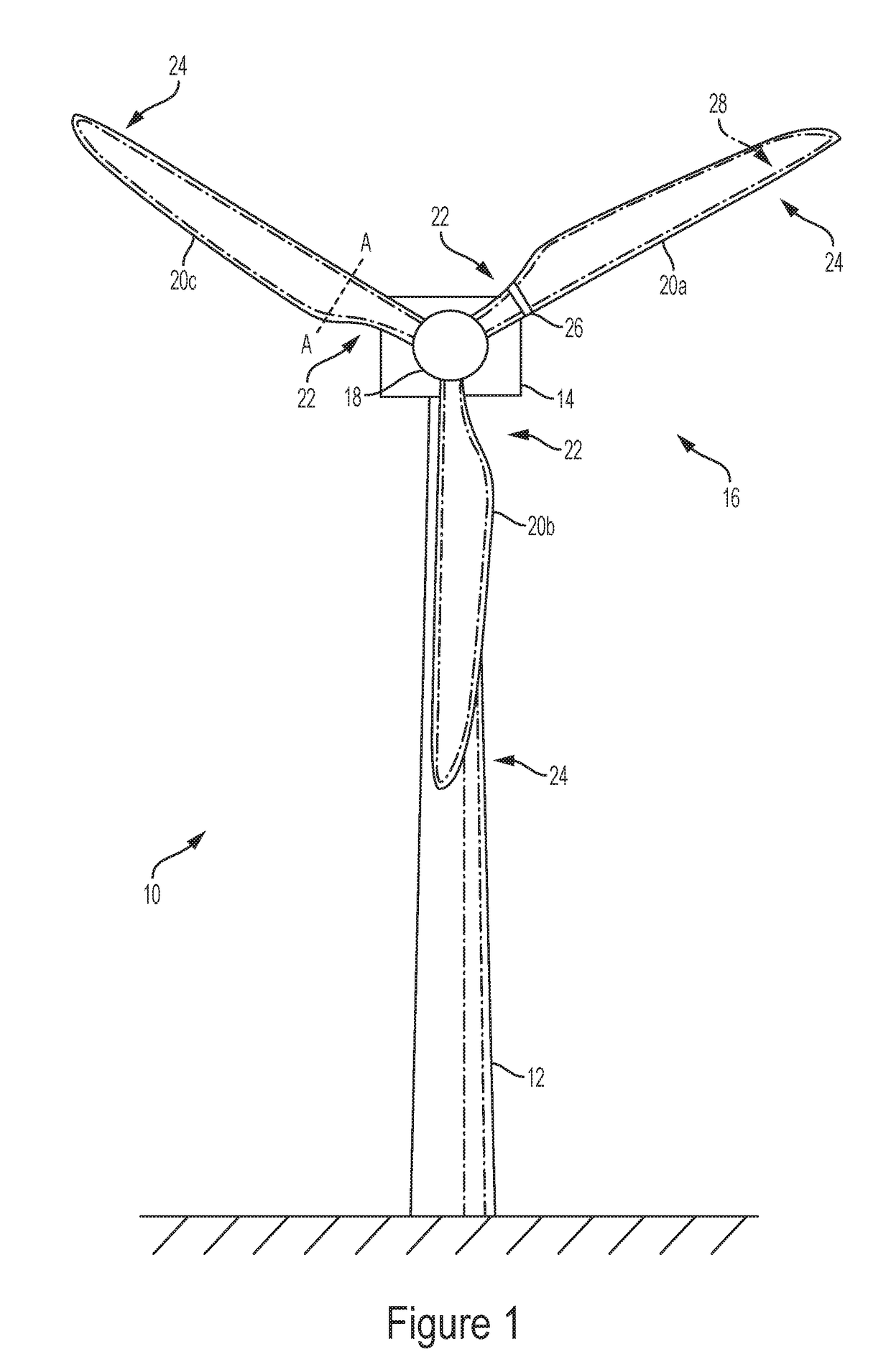
[0032]FIG. 1 is a schematic view of a wind turbine according to an embodiment of the present invention. A wind turbine 10 comprises a tower 12 on which a nacelle 14 is supported. A rotor 16 is mounted to the front of the nacelle 14. The rotor 16 comprises a hub 18 on which three equally-spaced rotor blades 20a, 20b, 20c are mounted. The rotor 16 includes a blade pitch system capable of varying the pitch angle of each rotor blade 20a, 20b, 20c independently, for example using an electric or hydraulic blade pitch drive.

[0033]In this embodiment, the rotor blades 20a, 20b, 20c each have a substantially cylindrical cross section at their root end 22. The cross section smoothly transitions to an aerofoil profile at a maximum c...


PUM


Abstract

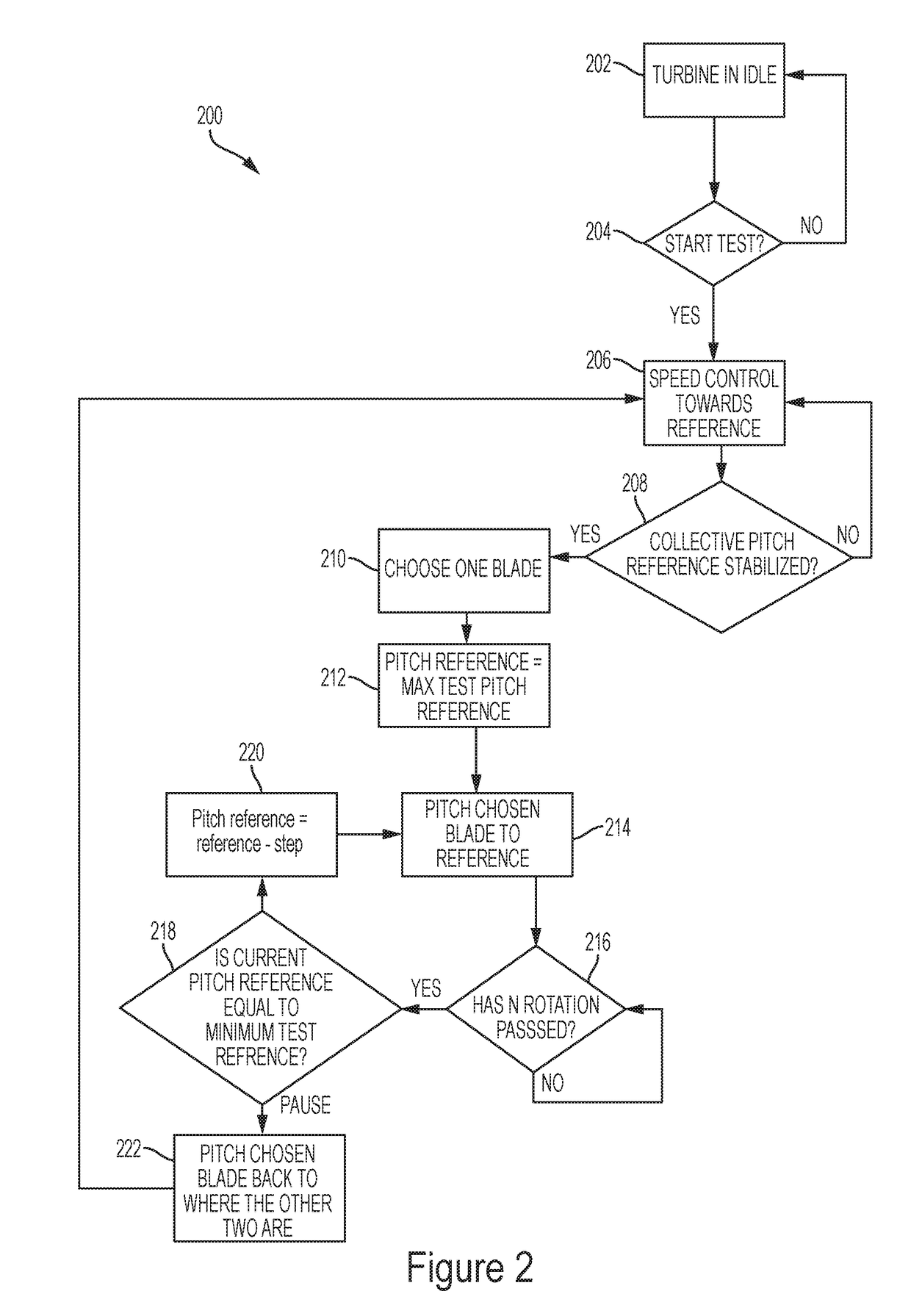
A method of calibrating load sensors of a wind turbine, and a wind turbine for such load sensor calibration, are disclosed. The wind turbine comprises a rotor, a plurality of rotor blades, and a plurality of load sensors associated with the rotor blades. While the rotor is rotating, at least one of the rotor blades is moved from a first calibration position to a second calibration position, and load values from the load sensors are measured. The number of rotor blades being moved is at least one fewer than the number of the plurality of rotor blades. The rotation of the rotor may be during idling of the wind turbine. The movement of the blade(s) may be to change the pitch angle of the blade(s). At least one of the rotor blades not being moved to a calibration position may also be moved, for example to control the rotational speed of the rotor.

Description

FIELD OF THE INVENTION[0001]This invention is directed to methods of calibrating load sensors of a wind turbine, and a wind turbine for such load sensor calibration.BACKGROUND OF THE INVENTION[0002]Loading on the components of wind turbines is carefully controlled, in order to maximise efficiency, and to minimise wear and damage. Load sensors are commonly mounted on wind turbines, typically on the rotor blades. These sensors require calibration in order to convert the values measured by these sensors to the actual loads on the turbine components.[0003]One previously considered method for calibrating these sensors is a calibration procedure in which the rotor is turned while the blades are at a fixed pitch angle. Other previous methods fix the rotor, so that it is immobile while measurements relating to the blade load sensors are taken, for example while one blade is horizontal. Such approaches may not be sufficient to provide the data needed for more sophisticated models of the forc...

Claims


Application Information

Patent Timeline
IPC IPC(8): F03D17/00F03D7/02G05B19/042
CPCF03D17/00F03D7/0224G05B19/042F05B2240/221F05B2270/802F05B2270/101G05B2219/2619F03D13/35Y02E10/72
Inventor CAPONETTI, FABIOOSTERGAARD, KASPER ZINCKHILTON, DAN
Owner VESTAS WIND SYST AS
Learn More