3D printer using linear laser source

a laser source and 3d printer technology, applied in the field of 3d printers, can solve the problems of complicated configuration of control units and increased size of light emission units, and achieve the effects of reducing the time taken to manufacture, reducing the emission time of laser beams, and simplifying the structure of apparatuses

Inactive Publication Date: 2018-05-24
SINDOH
View PDF30 Cites 3 Cited by
  • Summary
  • Abstract
  • Description
  • Claims
  • Application Information

AI Technical Summary

Benefits of technology

[0007]An object of the present invention is to provide a 3D printer using a linear laser source, the 3D printer controlling a light emission unit in a simple manner and having a simplified configuration.
[0019]According to the present invention, since the 3D printer has a structure in which a laser beam emitted from the light emission unit is linearly formed and travels horizontally, it is possible to simplify the structure of the apparatus in comparison to the related art, in which a galvanometer mirror is controlled along X and Y axes, and it is also possible to reduce the time taken to manufacture a 3D object by decreasing a laser beam emission time. Further, it is possible to simplify the control unit because only the light emission unit-carrying unit and the bed-carrying unit are controlled.

Problems solved by technology

However, 3D printers of the related art have a drawback in that the size of the light emission unit is increased by the structure of the galvanometer mirror, which is controlled along X and Y axes, and in that the configuration of a control unit is complicated because it is necessary to control the galvanometer mirror and the bed.

Method used


Image

  • 3D printer using linear laser source
  • 3D printer using linear laser source
  • 3D printer using linear laser source

Examples


Embodiment Construction

[0033]Hereinafter, exemplary embodiments of a 3D printer using a linear laser source according to the present invention are described in detail with reference to the accompanying drawings.

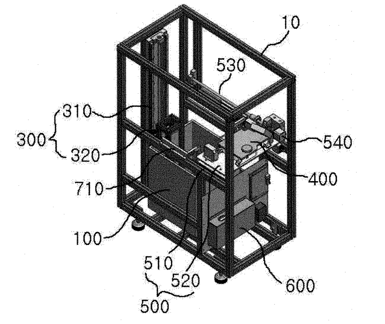
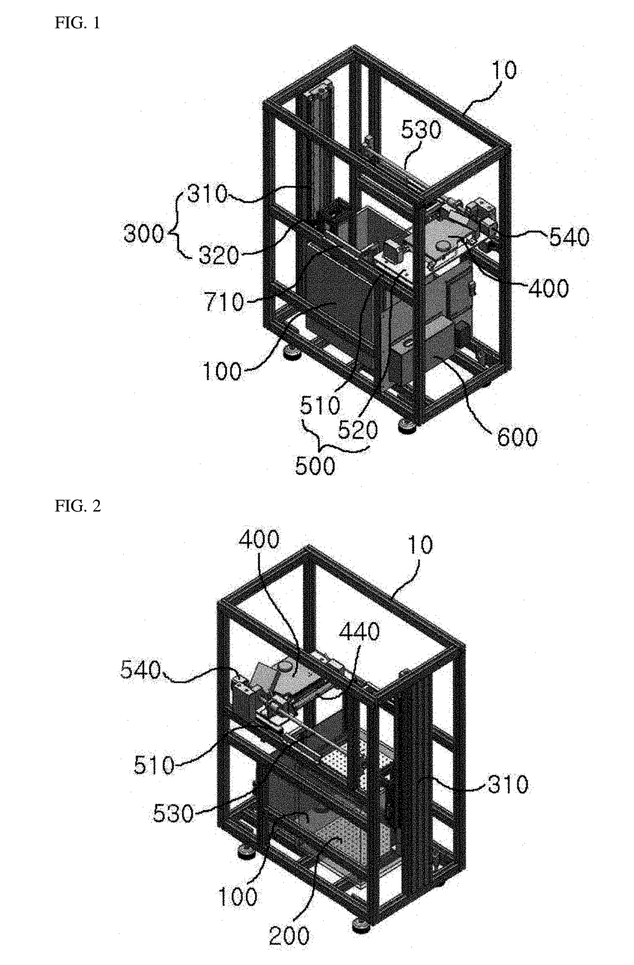
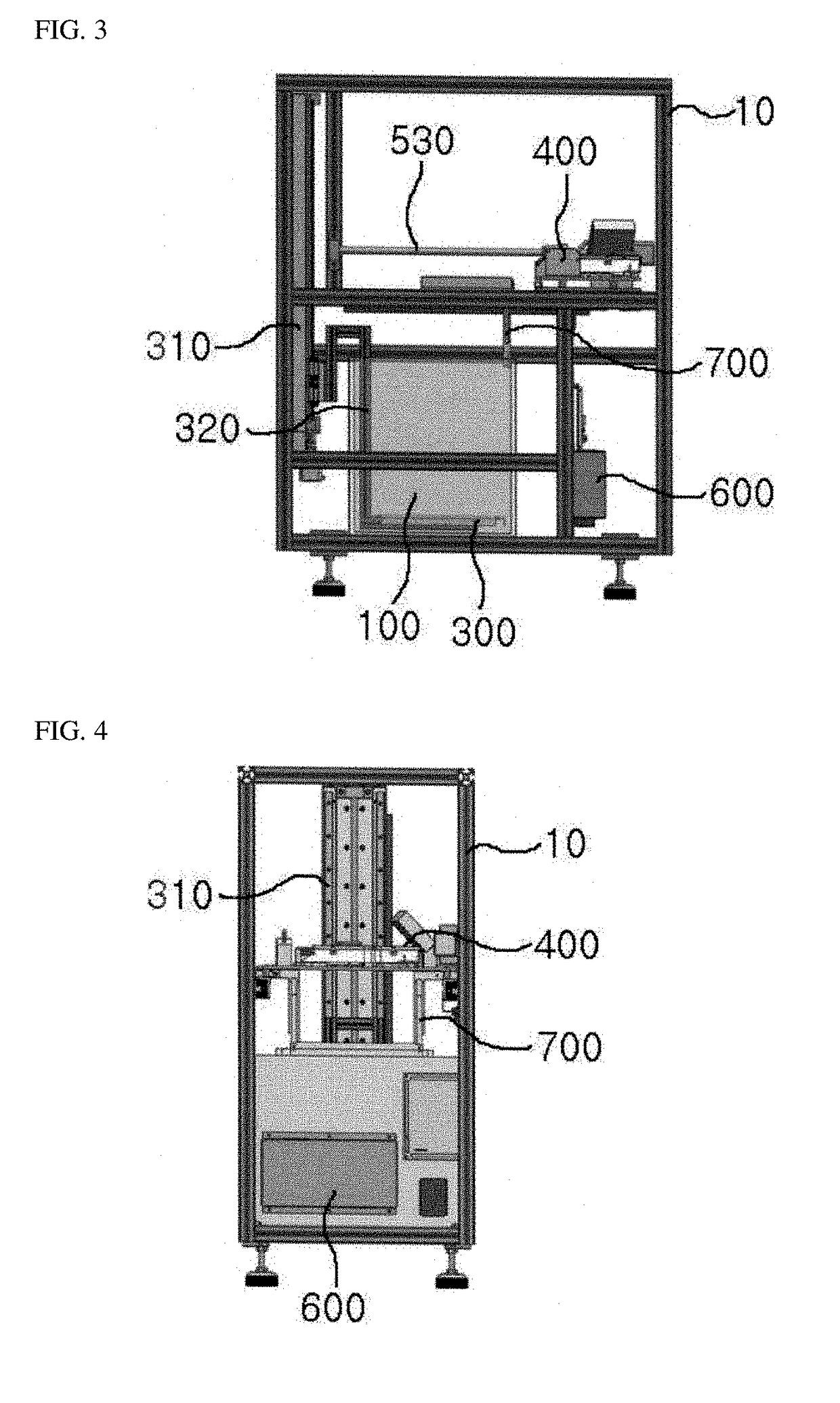
[0034]Referring to FIGS. 1 to 4, a 3D printer using a linear laser source according to the present invention includes: a vat 100 that contains liquid photocurable resin; a bed 200 that supports an object in the vat 100; a bed-carrying unit 300 that moves the bed 200; a light emission unit 400 that cures the liquid photocurable resin to form an object by radiating a laser beam to the liquid photocurable resin; a light emission unit-carrying unit 500 that moves the light emission unit 400; and a control unit 600 that controls the operation of the light emission unit 400, the light emission unit-carrying unit 500, and the bed-carrying unit 300.

[0035]The vat 100 is disposed at a lower portion inside a hexahedral frame 10 and liquid photocurable resin is stored in the vat 100.

[0036]The bed 200 supports ...


PUM

PropertyMeasurementUnit
poweraaaaaaaaaa
wavelengthaaaaaaaaaa
sizeaaaaaaaaaa

Abstract

The present invention provides a 3D printer using a linear laser source, the 3D printer including: a vat disposed at a lower portion inside a frame and configured to contain liquid photocurable resin therein; a bed configured to be vertically movable in the vat and to support an object; a bed-carrying unit configured to move the bed vertically; a light emission unit configured to cure the liquid photocurable resin in the vat to form the object by radiating a laser beam to the liquid photocurable resin in the vat; a light emission unit-carrying unit configured to move the light emission unit in the longitudinal direction of the vat; and a control unit configured to control operation of the light emission unit, the light emission unit-carrying unit, and the bed-carrying unit, wherein the light emission unit linearly emits a laser beam in the width direction of the vat.

Description

BACKGROUND OF THE INVENTION1. Field of the Invention[0001]The present invention relates to a 3D printer using a linear laser source, the 3D printer producing a 3D object by radiating a laser beam to liquid photocurable resin.2. Description of the Prior Art[0002]A 3D printer is a manufacturing apparatus that produces an object by continuously outputting layers of a material, like a 2D printer, and stacking the layers. 3D printers can quickly produce an object on the basis of digitized drawing information, so they are generally used to manufacture prototypes.[0003]As for the production method used by 3D printers, there are an SLA (Stereo Lithography Apparatus), which radiates a laser beam to a photocurable material so that the irradiated portion becomes a product, and an SLM (Selective laser melting), that melts and stacks thermoplastic filaments.[0004]Among the production methods employed by 3D printers, a 3D printer using SLA produces a 3D object by curing liquid photocurable resin ...

Claims


Application Information

Patent Timeline
Patent Type & Authority Applications(United States)
IPC IPC(8): B29C64/153B33Y10/00B33Y30/00G05B19/4099
CPCB33Y10/00B33Y30/00G05B19/4099G05B2219/49023B29C64/153B33Y50/02B29C64/135B29C64/268B29C67/0003B29C2035/0838B29C64/255B29C64/393B33Y40/20G02B5/09H01S3/0071
Inventor LEE, BYOUNG-BAGBAN, MIN-SUNGKIM, DONG-HEE
Owner SINDOH
Why Eureka
Try Eureka