Product discharge control device for a form-fill-seal machine

Active Publication Date: 2018-05-24
PAYPER
View PDF8 Cites 3 Cited by
  • Summary
  • Abstract
  • Description
  • Claims
  • Application Information

AI Technical Summary

Problems solved by technology

One of the drawbacks of using these discharge devices, using either a system for regulation by means of a cone system or else using a system for regulating discharge by means of a discharge blade system, is that the discharge is done directly of from the weighing unit (which weighs, meters and isolates the amount of product to be used for filling the bag) onto the discharge control device in the form-fill-seal machine and in synchronicity with the placement of the empty bag in the bag fill nozzle (with an advanced positioning of the discharge to optimize the moment of arrival of the product to the bag fill nozzle).
The fact that there is a coupling at the time of product discharge between both the weighing unit and the form-fill-seal machine means that at high working speeds one of them may condition the other and therefore mutually slow one another down due to synchronism.
This solution has some drawbacks: on one hand, the use of these devices controlled by pneumatic driving means for effecting the movements of the discharge blades has a limitation in controlling the opening and closing speeds, because the sudden stops upon reaching the end positions of the drives cause vibrations and collisions (p

Method used


Image

  • Product discharge control device for a form-fill-seal machine
  • Product discharge control device for a form-fill-seal machine
  • Product discharge control device for a form-fill-seal machine

Examples


second embodiment

[0027]FIG. 4 is an elevational view of the driving means of the product discharge control device of the present invention ; and

third embodiment

[0028]FIG. 5 is an elevational view of the driving means of the product discharge control device of the present invention according to a

DESCRIPTION OF A PREFERRED EMBODIMENT

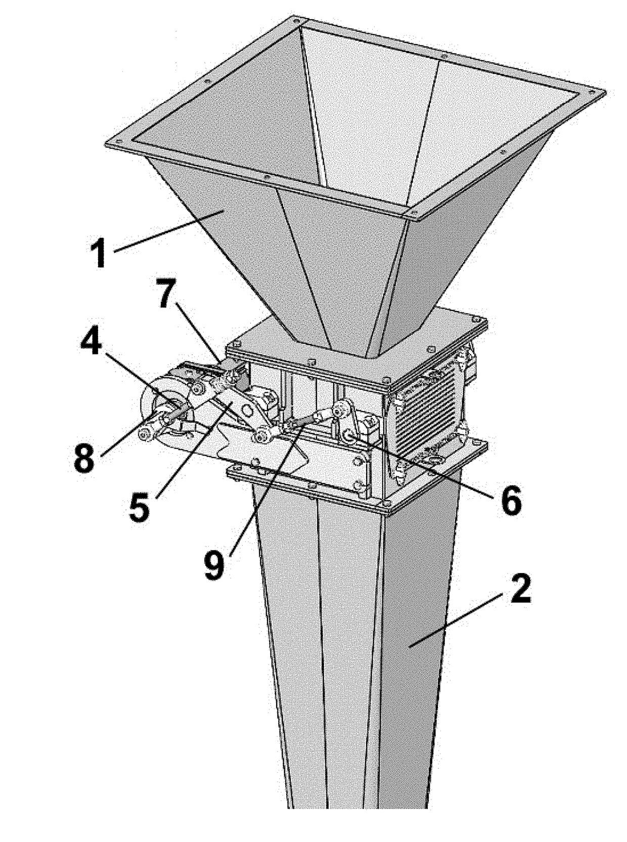
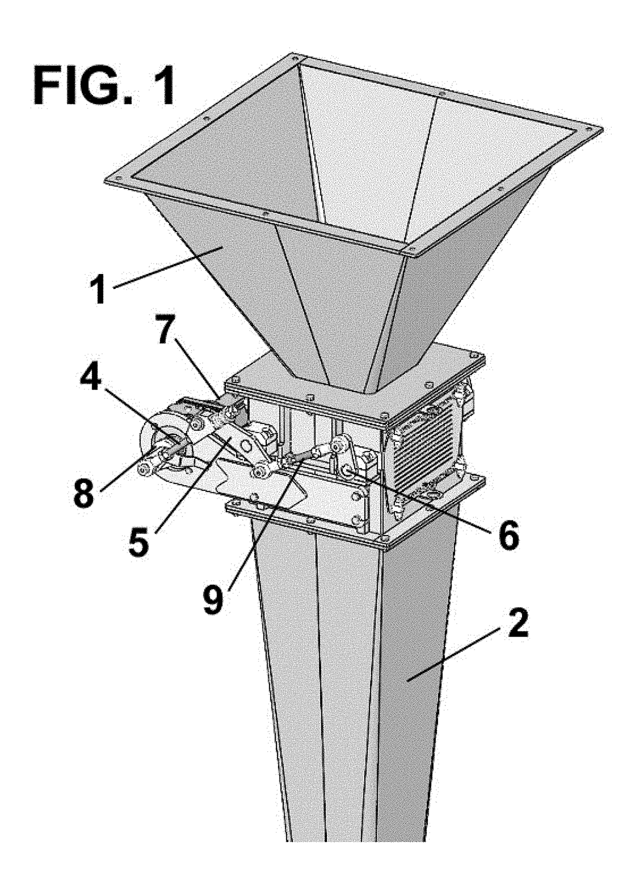
[0029]The drawings depict the product discharge control device according to the present invention, comprising a hopper 1 where the metered product amount used for filling the bag is discharged and a fill tube 2, connecting the discharge control device according to the present invention to the fill nozzle of the form-fill-seal machine.

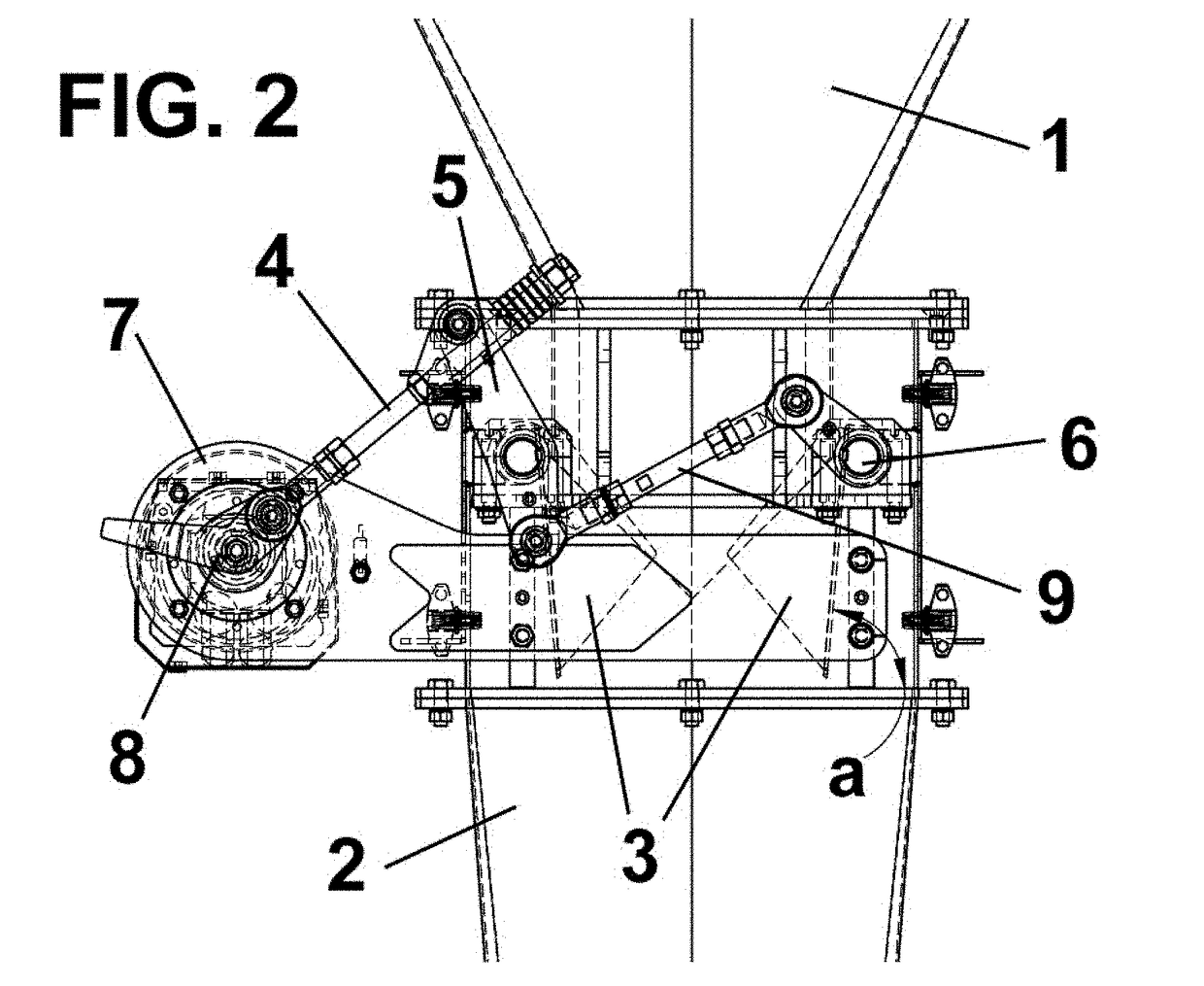
[0030]The control device according to the present invention also comprises discharge control elements 3 that are movable between an open position in which product discharge is allowed, and a closed position in which product discharge is prevented, which allows receiving in this closed position a new metered product amount discharge released by the metering and weighing system located upstream.

[0031]Said discharge control elements 3 are arranged between the hopper 1 and the fill tube ...

first embodiment

[0048]For the sake of simplicity, the same reference numbers are used to indicate elements equivalent to the preceding embodiment. It should furthermore be indicated that only the driving means of the discharge control elements are different in this embodiment, the remaining elements being the same as in the

[0049]In this embodiment, the driving means of the discharge control elements also comprise first and second levers 5, 6 connected by means of said synchronizing connecting rod 9, each integral with a shaft for moving each of said discharge control elements 3, and the movement of which is driven by means of a drive belt 10 located between the output shaft of the motor 7, preferably a servomotor, and one of said levers 5, 6.

[0050]FIG. 5 shows a third embodiment of the discharge control device according to the present invention.

[0051]Like in the preceding case, for the sake of simplicity, the same reference numbers are used to indicate elements equivalent to the preceding embodimen...


PUM

PropertyMeasurementUnit
Angleaaaaaaaaaa
Angleaaaaaaaaaa

Abstract

The invention relates to a discharge control device, comprising a hopper (1) receiving a metered product amount where it is deposited, discharge control elements (3) movable between a closed position and an open position by driving means, and a fill tube (2) connecting the discharge control device with a fill nozzle of the form-fill-seal machine whereby a bag is filled with product, wherein the driving means of the discharge control elements (3) comprise a motor (7) driving the movement of one of the discharge control elements (3), and a synchronizing connecting rod (9) synchronizing the movement of the discharge control element (3) driven by the motor (7) with the other discharge control element (3).
The invention allows filling bags reliably and more quickly.

Description

[0001]The present invention relates to a product discharge control device for a form-fill-seal machine which allows filling bags reliably and more quickly.BACKGROUND OF THE INVENTION[0002]Form-fill-seal machines, referred to as FFS machines, using a tubular reel of plastic material are known, and the process starts from a tubular reel for forming a bag having a given length, which bag is filled with a product and is closed or sealed once it is filled.[0003]One of the most important work stations in this process is the fill station, in which the bag previously formed in a previous station and transferred to the fill station by conveyance means is opened at the upper part to allow the bag fill nozzle to enter the bag and discharge the product that has been prepared upstream from the bag fill nozzle through the passage formed by blades of the nozzle as they open.[0004]In this station, the bag is filled with the metered product amount by means of using a discharge device located upstrea...

Claims


Application Information

Patent Timeline
IPC IPC(8): B65B39/00B65B37/02B65B9/10B65B37/18
CPCB65B39/002B65B37/02B65B9/10B65B37/18B65B43/00B65B1/06B65B1/32B65B1/02B65B57/145B65B1/30
Inventor CURCO MASIP, CARMELOBONET ROSELL, GIL
Owner PAYPER
Why Eureka
Try Eureka