A device and method for moving a jet member

a jet member and jet body technology, applied in the direction of spraying apparatus, roads, roads, etc., can solve the problems of difficult to fill the pits with concrete, the treatment will not be uniform, and the formation of so-called pits or bore holes

Active Publication Date: 2018-05-31
AQUAJET SYST HLDG
View PDF1 Cites 2 Cited by
  • Summary
  • Abstract
  • Description
  • Claims
  • Application Information

AI Technical Summary

Benefits of technology

[0018]According to another embodiment of the invention said first movability is a pivotability of the jet member around a first axis extending in parallel with said first path. This constitutes an advantageous way of achieving said first movability.
[0

Problems solved by technology

By using a small attack angle, i.e. an angle of the jet being substantially perpendicular to the layer to be treated, the material may be removed quickly, but the result of the treatment will not be that uniform.
This means that the exposure time of the layer for said jet member (impact point) will be longer at said end positions resulting in a deeper material removal there resulting in a formation of so called pits or bore holes.
It will then be difficult to fill these pits with concrete when subsequently app

Method used


Image

  • A device and method for moving a jet member
  • A device and method for moving a jet member
  • A device and method for moving a jet member

Examples


Embodiment Construction

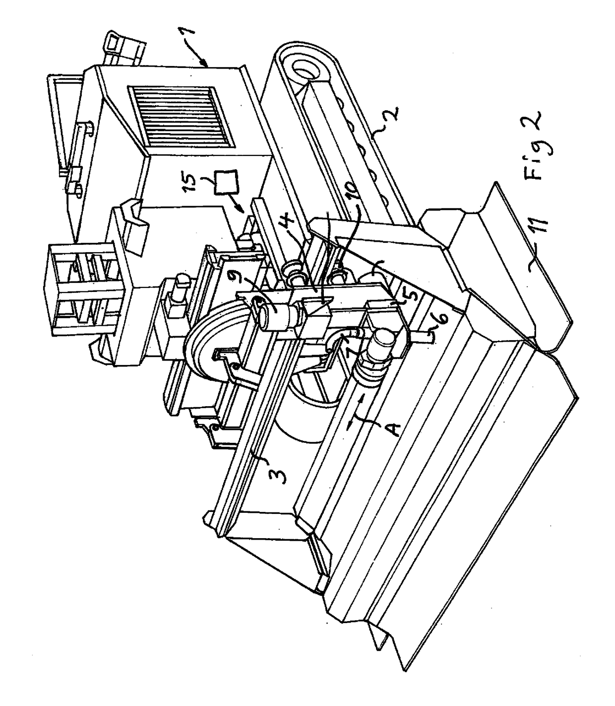
[0034]The general structure of a device according to the present invention and how it may be used will first of all be described with reference made to FIGS. 2-5 showing a said device arranged on a mobile unit 1, which has the character of a vehicle movable on the bedding, for instance a concrete layer, to be treated. The vehicle is indicated as being of crawler type with two driving tracks 2.

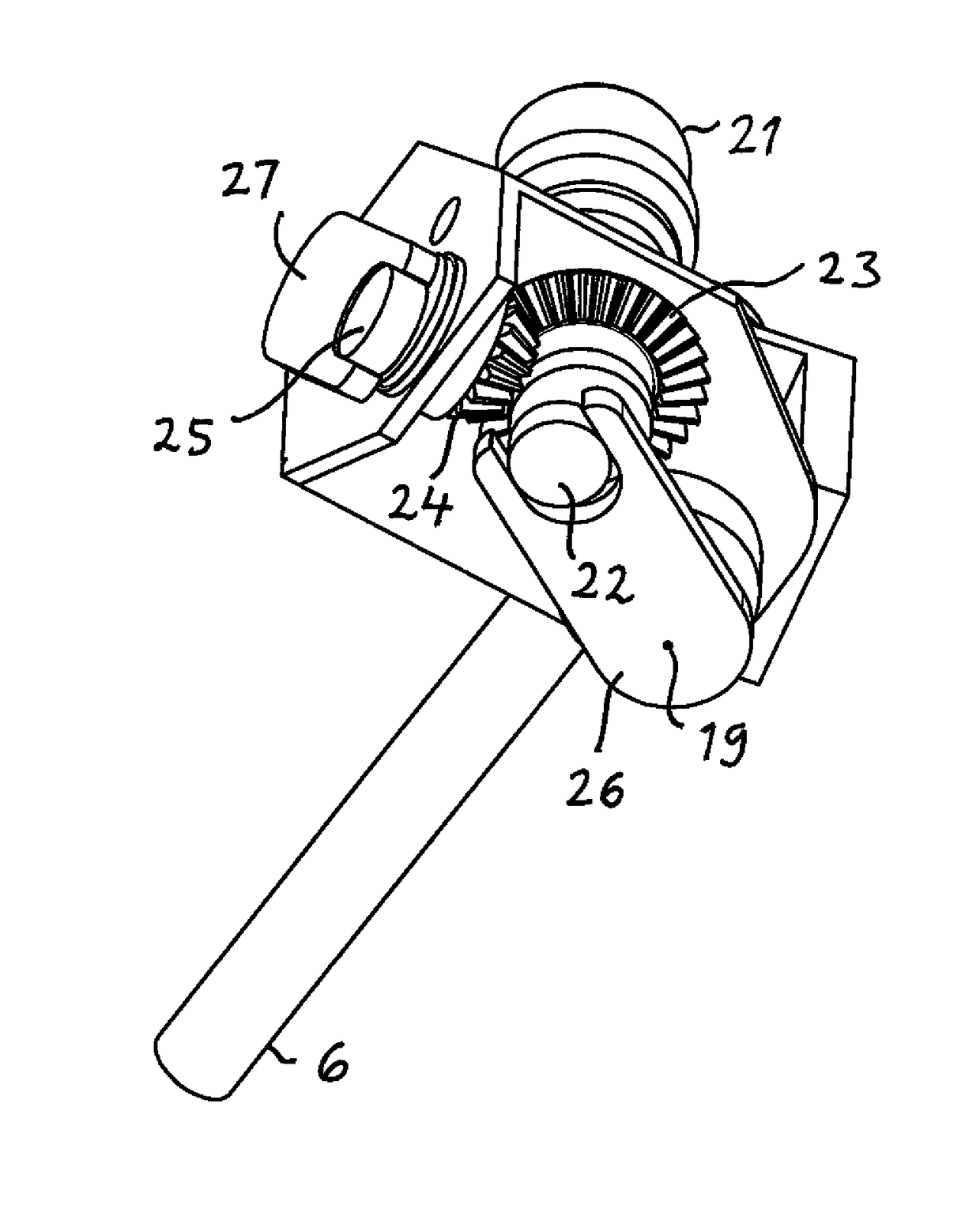
[0035]An elongated guide member 3 of the device is arranged on the vehicle 1, and a carriage 4 is movable in a substantially rectilinear first path to and fro along said guide member for carrying out so called traverses. A base portion 5 constitutes a part of the carriage 4. A tube-like jet member 6 or lance is arranged on the base portion 5 for directing a high pressure jet of liquid against the bedding. The guide member in operation is intended to make an angle preferably substantially a right angle, with a motion direction of the vehicle. The jet member 6 communicates through a conduit 7 wit...


PUM


Abstract

A device for moving a jet member (6) having a nozzle comprises a carriage (4) with a base portion (5) to which the jet member is connected. The carriage is movable in a substantially rectilinear first path along a guide member (3). The connection of the jet member to the base portion provides a movability of the jet member (6) with respect to the base portion (5) and by that said carriage comprising a movability of the jet member for moving an impact point of the jet in a second path perpendicularly to said first path. A control unit is controlling a driving arrangement to combine a movement of the carriage along the guide member (3) and a movement of the jet member with respect to the base portion of the carriage so as to make an impact point of the jet on a said layer to travel with a constant speed over the layer.

Description

TECHNICAL FIELD OF THE INVENTION AND BACKGROUND ART[0001]The present invention relates to a device for moving a jet member having a nozzle, said device comprising[0002]a carriage provided with a base portion to which said jet member is connected,[0003]a guide member along which said carriage is movable in a substantially rectilinear first path for moving the nozzle of the jet member over a layer to be treated by the jet, the connection of said jet member to said base portion providing a movability of the jet member with respect to the base portion and by that said carriage comprising a first movability of the jet member for moving an impact point of said jet in a second path perpendicularly to said first path,[0004]a driving arrangement configured to move said carriage along said first path and said jet member with respect to said base portion of said carriage, and[0005]a control unit configured to control said driving arrangement for controlling the movement of said impact point of...

Claims


Application Information

Patent Timeline
IPC IPC(8): B05B13/04B05B13/00E01C23/12E01C23/08
CPCB05B13/0415B05B13/005E01C23/128E01C23/08
Inventor HILMERSSON, RONNIE
Owner AQUAJET SYST HLDG
Why Eureka
Try Eureka