
LED driver and an LED driving method

a technology of led driver and led driving method, which is applied in the direction of electric variable regulation, process and machine control, instruments, etc., can solve the problems of significant additional control circuitry, excessive current flow, and out of control current flow, and achieve low cost, high performance and reliability, and low number of components

Inactive Publication Date: 2018-05-31
SIGNIFY HLDG BV
View PDF0 Cites 7 Cited by
  • Summary
  • Abstract
  • Description
  • Claims
  • Application Information

AI Technical Summary

Benefits of technology

The invention is a soft start circuit for a driver that has a low number of components, low cost, and high performance and reliability. The circuit generates an output when there is no sensor signal to protect the main converter switch and limit current flow even when the sensor is not active. When the sensor is active, it takes control of the main converter switch to achieve efficient conversion. The processing circuit is easy to implement and can change the bias of the control transistor to alter the switching cycles of the main converter switch. Overall, the invention provides a simple and effective solution for starting up a driver.

Problems solved by technology

However, there may be a delay before the feedback mechanism is effective, so that at start-up of the power converter, the currents flowing may be out of control.
For example, if there is a short circuit condition at the output when the power converter is initially turned on, excessive currents may flow before the feedback mechanism is able to regulate the system.
However, this generally requires significant additional control circuitry and is therefore expensive to implement.

Method used


Image

  • LED driver and an LED driving method
  • LED driver and an LED driving method
  • LED driver and an LED driving method

Examples


Embodiment Construction

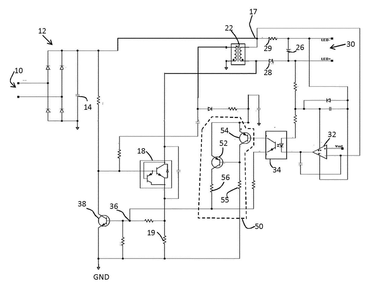
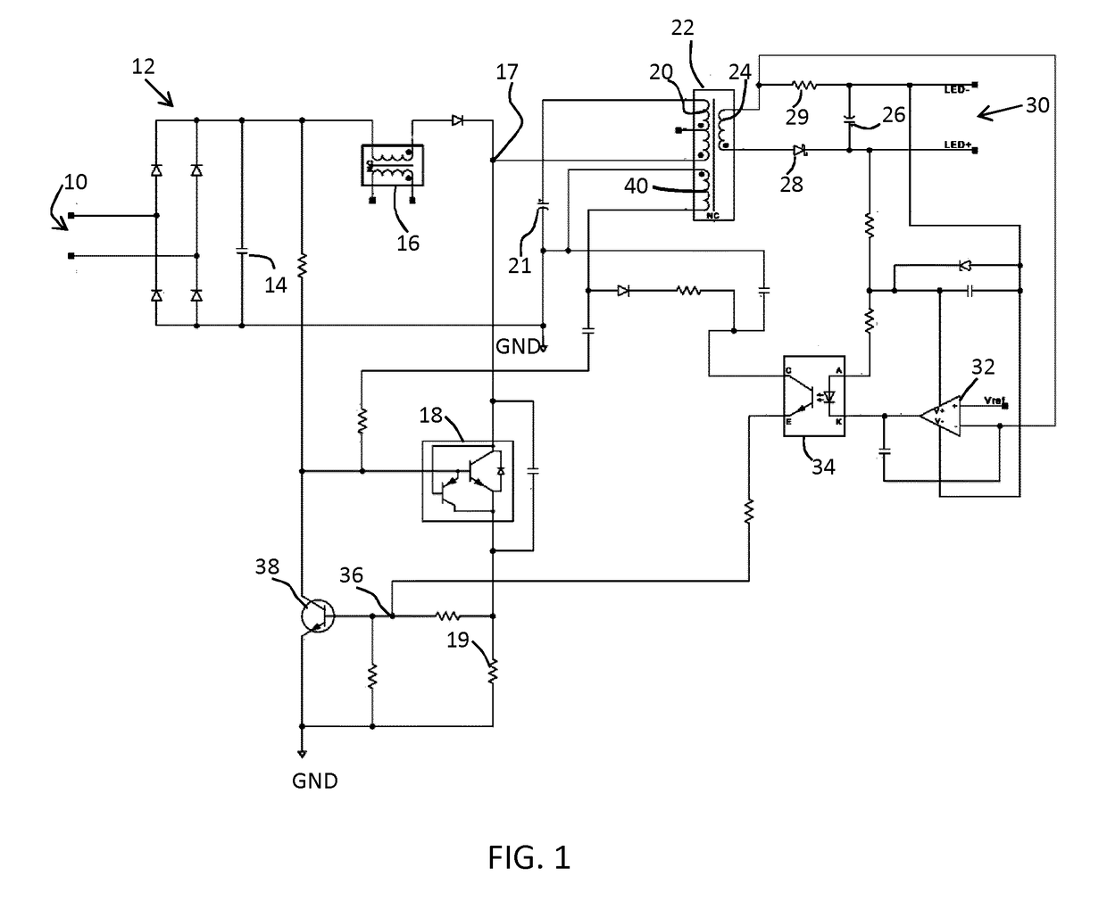
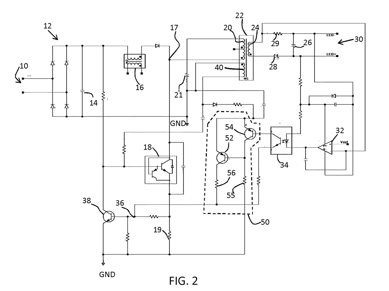
[0057]The invention provides an LED driver, comprising an inductive switch mode converter which uses a feedback arrangement for controlling the main converter switch. A processing circuit is used to process a feedback sensor signal so that an output is generated even when there is no feedback sensor signal. This output is used to limit the current flowing through the main converter switch when no sensor signal is present, and it provides a soft start function.

[0058]Embodiments of the invention provides a protection mechanism which is of general applicability to an inductive switch mode converter in which a feedback signal is used to regulate the output.

[0059]By way of example only, the invention will be described as applied to a ringing choke isolated converter architecture. The ringing choke circuit provides the cyclic control of the main converter switch of the switch mode converter (rather than using a pulse width modulation circuit, for example), and the isolation is provided by...


PUM


Abstract

An LED driver, comprising: an inductive switch mode converter having an inductive component (16,22), an LED output (30) for an LED load and a main converter switch (18) for controlling a current flowing through the inductive component; a sensor (32) for generating a sensor signal indicative of the output current or voltage provided to the LED output; a feedback element (34) which provides a feedback path for feeding back the sensor signal for control of the main converter switch (18); and a processing circuit (50) for processing the sensor signal which has been fed back, wherein the processing circuit is adapted to generate an output when there is no sensor signal so as to limit the current flowing through the main converter switch when no sensor signal is present.

Description

FIELD OF THE INVENTION[0001]The invention relates to an LED driver and an LED driving method. It relates in particular to a driving method in which a power converter which drives an LED arrangement is controlled using a feedback signal.BACKGROUND OF THE INVENTION[0002]In an LED driver which uses feedback, a signal representing the voltage at the output or the current flowing to the output is fed back to enable control of the power converter.[0003]The power converter typically comprises an inductive switch mode power supply. The current flowing through an inductive element is controlled by a main converter switch, and the duty cycle with which the switch is controlled determines the power conversion ratio.[0004]It is required to prevent that the inductive element becomes saturated, since the current can then run out of control. In normal operation, the feedback mechanism prevents this saturation. However, there may be a delay before the feedback mechanism is effective, so that at sta...

Claims


Application Information

Patent Timeline
Patent Type & Authority Applications(United States)
IPC IPC(8): H05B33/08H02M3/335H02M1/42H02M1/36H05B44/00H05B45/50
CPCH05B33/0887H05B33/0815H02M3/33553H02M1/4266H02M1/36H02M2001/0009H02M2001/0025H02M1/4225H02M1/4258H02M3/3385H05B45/50H05B45/10Y02B70/10H05B45/385H02M1/0009H02M1/0025
Inventor SUN, SHIGUANGLIU, LYLEZHOU, LIWEN
Owner SIGNIFY HLDG BV
Learn More