Automatic target recognition and management system

Active Publication Date: 2018-06-07
AGERRIS PTY LTD
View PDF21 Cites 36 Cited by
  • Summary
  • Abstract
  • Description
  • Claims
  • Application Information

AI Technical Summary

Benefits of technology

[0021]In one embodiment, the resilient bias mechanism takes the form of one or more mechanical springs. In other embodiments, the resilient bias mechanism takes the form of elastic straps or bands. In yet other embodiments, pneumatic or electromagnetic spring mechanisms may be used. The spring mechanism may be fixed, statically adjustable or dynamically adjustable, for example to accommodate different degrees of soil hardness or compaction, different varieties of weeds or crops, different configurations of tines, and other relevant factors. Additionally, the actuation mechanism may be operated so as to emulate a dynamic spring, for example by operating the controller in torque mode, whereby torque can be sensed through changes in current, hydraulic pressure, pneumatic pressure, or by means of torque sensors. Complementary damping elements may also be incorporated into the spring mechanism and again these elements may be fixed, statically adjustab

Problems solved by technology

Consequently, the emergence of weeds has a marked adverse impact on crop yield and quality.
Moreover, due to their relatively fast growth rates compared to crops, if weeds are not eliminated or effectively managed, particularly during the early stages after crop planting, they can quickly dominate entire fields and result in serious yield losses.
However, a number of associated problems and limitations have emerged including the cost of these agricultural chemicals and associated application equipment, short and longer-term environmental toxicity effects, human toxicity effects including in some cases carcinogenic effects, increased herbicide resistance and incompatibilit

Method used


Image

  • Automatic target recognition and management system
  • Automatic target recognition and management system
  • Automatic target recognition and management system

Examples


Example

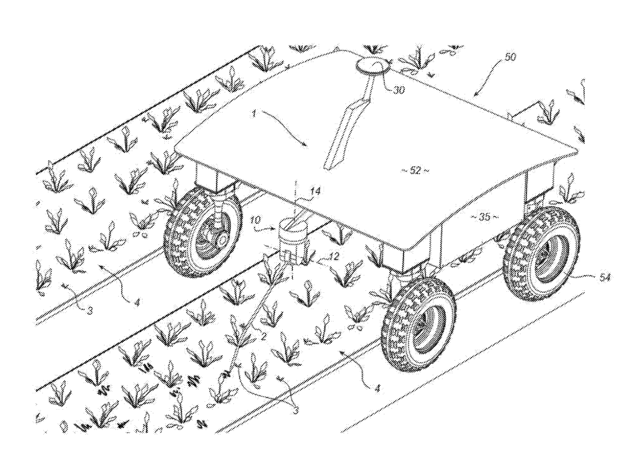
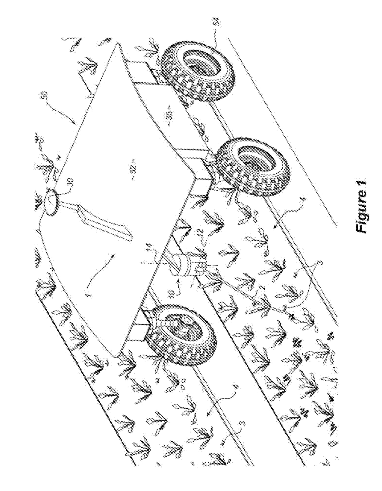
[0080]Referring initially to FIGS. 1 and 2, the invention provides an autonomous weeding apparatus 1. The apparatus includes a tine formation 2 adapted to remove, dislodge or disrupt targeted weeds 3 as the tine is drawn along a planted row or seed bed 4.

[0081]A tine support assembly 10 is adapted to support the tine 2 for movement in a generally vertical direction about a horizontally oriented first control axis 12. In this way, the tine is movable in use between a downwardly oriented engaged position (as shown in FIG. 1) wherein the tine contacts or penetrates the ground surface for removal or disruption of the targeted weeds, and an upwardly oriented disengaged position wherein the tine is substantially retracted from the ground surface. The tine support assembly 10 is further adapted to support the tine for movement in a generally horizontal direction about a vertically oriented second control axis 14. In this embodiment, the tine support assembly takes the form of a turret prov...


PUM


Abstract

This invention relates to an apparatus for controlling weeds. The apparatus includes a tine formation adapted to remove or disrupt targeted weeds, and a tine support assembly adapted to support the tine for movement about a first control axis in a generally vertical direction between an engaged position wherein the tine formation in use contacts a ground surface for removal or disruption of targeted weeds and a disengaged position wherein the tine formation is substantially retracted from the ground surface. The tine support assembly is further adapted to support the tine for movement about a second control axis in a generally horizontal direction. The tine support assembly further includes a first actuation mechanism adapted to effect movement of the tine about the first control axis, and a second actuation mechanism adapted to effect movement of the tine about the second control axis. The apparatus also includes a sensing system for sensing aspects of an environment and generating data indicative thereof, and a classification system for identifying target weeds within the environment on the basis of the data from the sensing system. A control system is adapted to activate the first and second actuation mechanisms of the tine support assembly in accordance with a predetermined control logic thereby sequentially to position the tine for disruptive contact with the targeted weeds.

Description

FIELD OF THE INVENTION[0001]The present invention relates generally to an automated apparatus, method and system for managing weeds or similar pests in the context of agriculture, plant cultivation or environmental management.[0002]The invention has been developed primarily for targeting and mechanical removal of weeds and will be described predominantly in this context. It should be appreciated, however, that the invention is not limited to this field of use, being potentially also adaptable for feeding or watering plants, harvesting produce, pollinating plants, trimming, pruning or thinning foliage, or other analogous purposes wherein the targeting and end-effector positioning systems may be effectively utilised. The invention is also potentially adaptable for identifying and controlling pests and diseases, in particular being potentially adaptable for detecting, controlling and / or removing foreign bodies from a site or predetermined region such as, for example, sticks, bones, mic...

Claims


Application Information

Patent Timeline
IPC IPC(8): A01B39/18A01B79/00A01M21/04
CPCA01B39/18A01B79/005A01M21/043A01M21/02A01M21/04A01B51/02A01B69/001A01B63/004A01B63/023A01B63/104A01B63/1112A01B63/12A01B61/046
Inventor CALLEIJA, MARKSUKKARIEH, SALAH
Owner AGERRIS PTY LTD
Why Eureka
Try Eureka