Imaging devices having piezoelectric transducers

a piezoelectric transducer and imaging device technology, applied in the field of imaging devices, can solve problems such as transmission and receive inefficiencies, particularly prone to failure or drift of conventional cmut sensors,

Active Publication Date: 2018-06-07
EXO IMAGING INC
View PDF4 Cites 23 Cited by
  • Summary
  • Abstract
  • Description
  • Claims
  • Application Information

AI Technical Summary

Benefits of technology

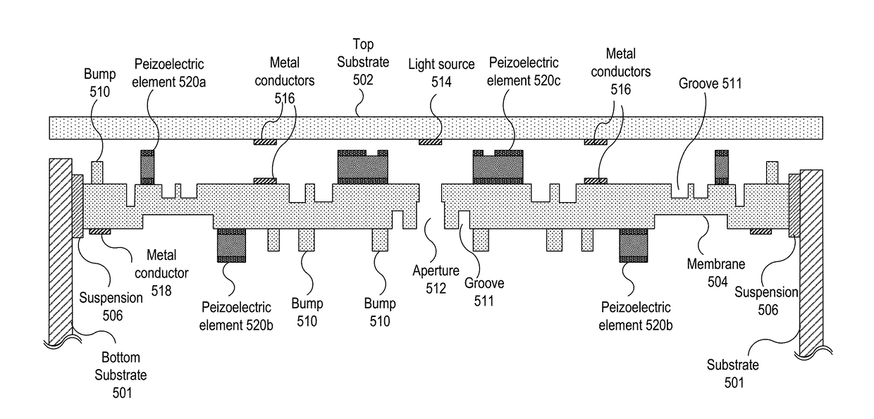
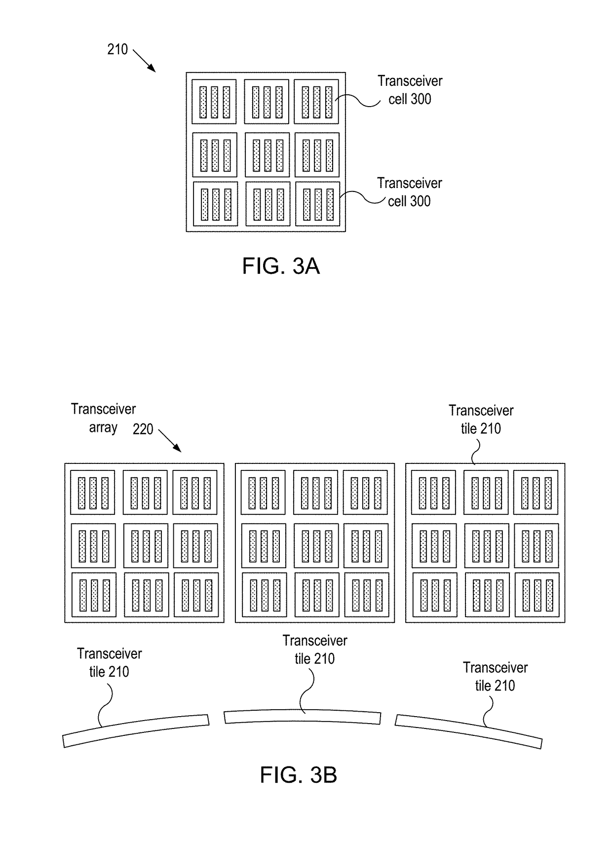
[0007]In embodiments, an imaging system includes: a transceiver cell for generating a pressure wave and converting an external pressure wave into an electrical signal; and a control unit for controlling an operation of the transceiver cell. The transceiver cell includes: a substrate; at least one membrane suspending from the substrate; and a plurality of transducer elements mounted on the at least one membrane, each of the plurality of transducer elements having a bottom electrode, a piezoelectric layer on bottom electrode, and at least one top electrode on the piezoelectric layer, each of the plurality of transducer element generating a bending moment in response to applying an electrical potential across the bottom electrode and the at least one top electrode and developing an electrical charge in response to a bending moment due to the external pressure wave.

Problems solved by technology

Although the basic concepts for these transducers have been disclosed in the early 1990's, commercial implementation of these concepts has met with a number of challenges.
For instance, the conventional cMUT sensors are particularly prone to failure or drift in performance due to the dielectric charge build-up during operation.
The conventional pMUTs have been a promising alternative but have issues related to transmission and receive inefficiencies.

Method used


Image

  • Imaging devices having piezoelectric transducers
  • Imaging devices having piezoelectric transducers
  • Imaging devices having piezoelectric transducers

Examples


Embodiment Construction

[0040]In the following description, for purposes of explanation, specific details are set forth in order to provide an understanding of the disclosure. It will be apparent, however, to one skilled in the art that the disclosure can be practiced without these details. Furthermore, one skilled in the art will recognize that embodiments of the present disclosure, described below, may be implemented in a variety of ways, such as a process, an apparatus, a system, or a device.

[0041]Elements / components shown in diagrams are illustrative of exemplary embodiments of the disclosure and are meant to avoid obscuring the disclosure. Reference in the specification to “one embodiment,”“preferred embodiment,”“an embodiment,” or “embodiments” means that a particular feature, structure, characteristic, or function described in connection with the embodiment is included in at least one embodiment of the disclosure and may be in more than one embodiment. The appearances of the phrases “in one embodime...


PUM


Abstract

An imaging system includes: a transceiver cell for generating a pressure wave and converting an external pressure wave into an electrical signal; and a control unit for controlling an operation of the transceiver cell. The transceiver cell includes: a substrate; at least one membrane suspending from the substrate; and a plurality of transducer elements mounted on the at least one membrane. Each of the plurality of transducer elements has a bottom electrode, a piezoelectric layer on bottom electrode, and at least one top electrode on the piezoelectric layer. Each of the plurality of transducer element generates a bending moment in response to applying an electrical potential across the bottom electrode and the at least one top electrode and develops an electrical charge in response to a bending moment due to the external pressure wave.

Description

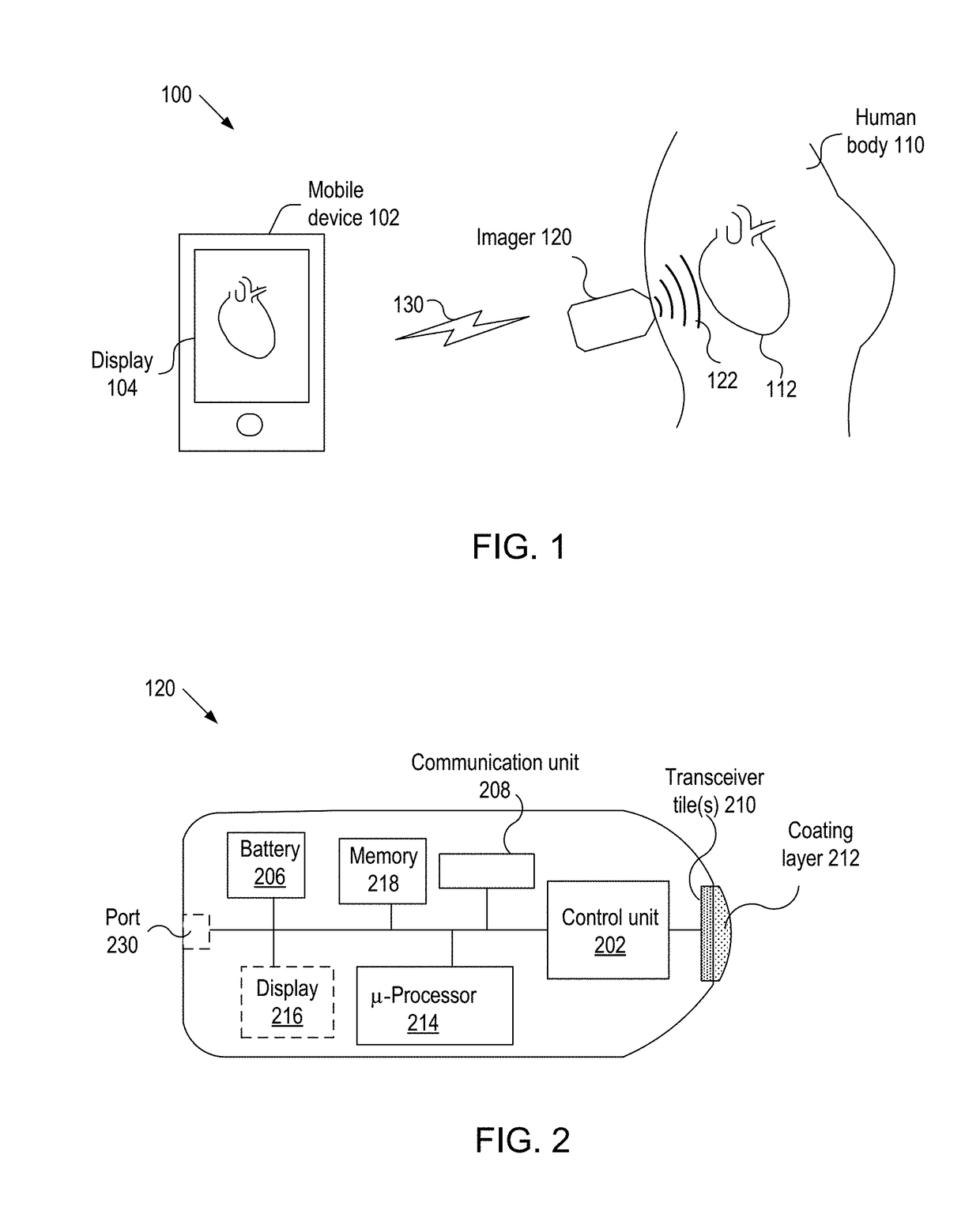
BACKGROUND[0001]A. Technical Field[0002]The present invention relates to imaging devices, and more particularly, to imaging devices having piezoelectric transducers.[0003]B. Background of the Invention[0004]A non-intrusive imaging system for imaging internal organs of a human body and displaying images of the internal organs transmits signals into the human body and receives signals reflected from the organ. Typically, transducers that are used in an imaging system are referred to as transceivers and some of the transceivers are based on photo-acoustic or ultrasonic effects. In general, piezoelectric transducers are used for imaging as well as other applications, such as medical imaging, flow measurements in pipes, speaker, microphone, lithotripsy, heating tissue for therapeutics, and highly intensive focused ultrasound (HIFU) for surgery.[0005]Advances in micro-machining technologies allow sensors and actuators to be efficiently incorporated on a substrate. In particular, micromach...

Claims


Application Information

Patent Timeline
Patent Type & Authority Applications(United States)
IPC IPC(8): A61B8/00B06B1/06B06B1/02G01S7/52A61B8/08A61B8/14
CPCA61B8/4494B06B1/0629B06B1/0238G01S7/52046A61B8/4488A61B8/461A61B8/5207A61B8/145A61B8/0883A61B8/4483A61B5/0059A61B5/0095B06B1/0607B06B1/0692G01S7/52079A61B8/4427B06B1/0662G01S15/8925A61B8/4472B06B1/0215B06B2201/76G01S7/5208H10N30/2047H10N30/88H10N30/1051H10N30/2048A61B8/546G01S7/521A61B8/488
Inventor AKKARAJU, SANDEEPKWON, HAESUNGHAQUE, YUSUFBRYZEK, JANUSZ
Owner EXO IMAGING INC
Why Eureka
Try Eureka