
Finger follower assembly for use in a valvetrain of an internal combustion engine

a technology of internal combustion engine and valvetrain, which is applied in the direction of valve arrangement, machines/engines, mechanical equipment, etc., can solve the problems of significantly reducing engine life, affecting engine performance, and not easily achievable and/or practical, so as to reduce the complexity and packaging size of the valvetrain system and its associated components, facilitate the alignment of the bearing, and reduce the cost of manufacturing the valvetrain system

Active Publication Date: 2018-06-07
GT TECH INC
View PDF2 Cites 3 Cited by
  • Summary
  • Abstract
  • Description
  • Claims
  • Application Information

AI Technical Summary

Benefits of technology

The present invention simplifies and reduces the size of valvetrain systems, making them cheaper and more efficient. This results in improved engine performance, control, lubrication, and reduced vibration, noise, engine wear, and packaging size.

Problems solved by technology

Excessive tolerance results in detrimental engine performance as well as increased friction and wear of the various valvetrain components, which leads to significantly decreased engine life.
While effecting and maintaining proper alignment is desirable for engine valvetrain systems, in some applications it is not readily achievable and / or practical.
Nevertheless, misalignment between the camshaft lobe and the bearing of the finger follower typically results in undesirable wear, increased noise, increased component stress and / or load, decreased component life, and the like to the various components of the valvetrain.
Here too, misalignment between the body of the finger follower and the lash adjuster and / or valve typically results in undesirable wear, increased noise, increased component stress and / or load, decreased component life, and the like to the various components of the valvetrain.

Method used


Image

  • Finger follower assembly for use in a valvetrain of an internal combustion engine
  • Finger follower assembly for use in a valvetrain of an internal combustion engine
  • Finger follower assembly for use in a valvetrain of an internal combustion engine

Examples


Embodiment Construction

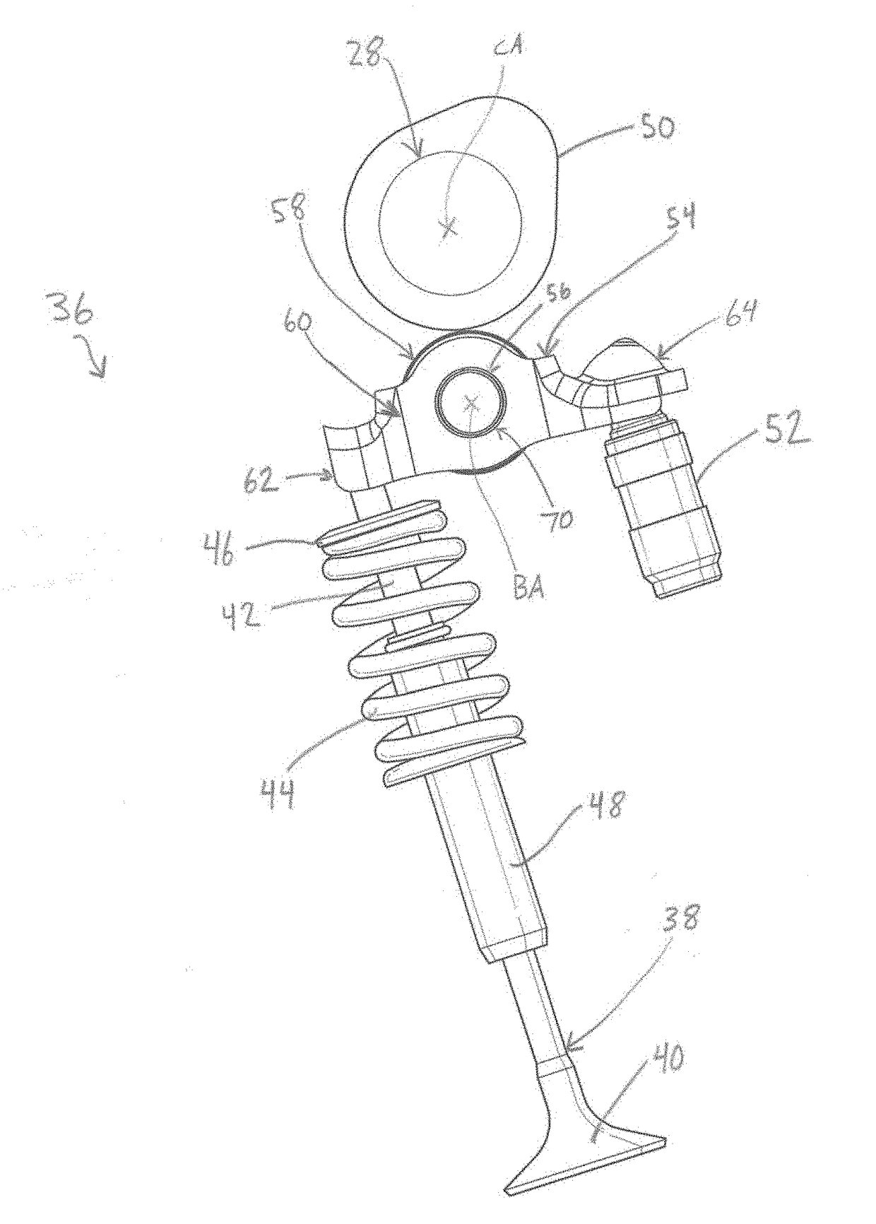
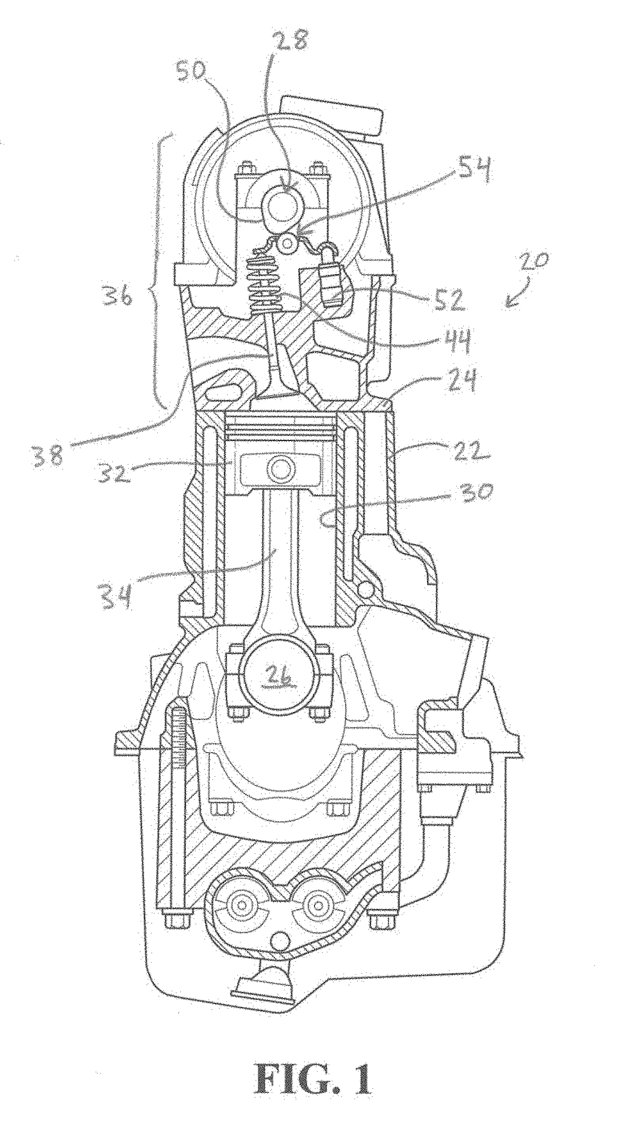
[0032]Referring now to the drawings, where like numerals are used to designate like structure, a portion of an internal combustion engine is illustrated at 20 in FIG. 1. The engine 20 includes a block 22 and a cylinder head 24 mounted to the block 22. A crankshaft 26 is rotatably supported in the block 22, and a camshaft 28 is rotatably supported in the cylinder head 24. The crankshaft 26 drives the camshaft 28 via a timing chain or belt (not shown, but generally known in the art). The block 22 typically includes one or more cylinders 30 in which a piston 32 is supported for reciprocal motion therealong. The piston 32 is pivotally connected to a connecting rod 34, which is also connected to the crankshaft 26. In operation, combustion in the cylinders 30 of the engine 20 moves the pistons 32 in reciprocal fashion within the cylinders 30.

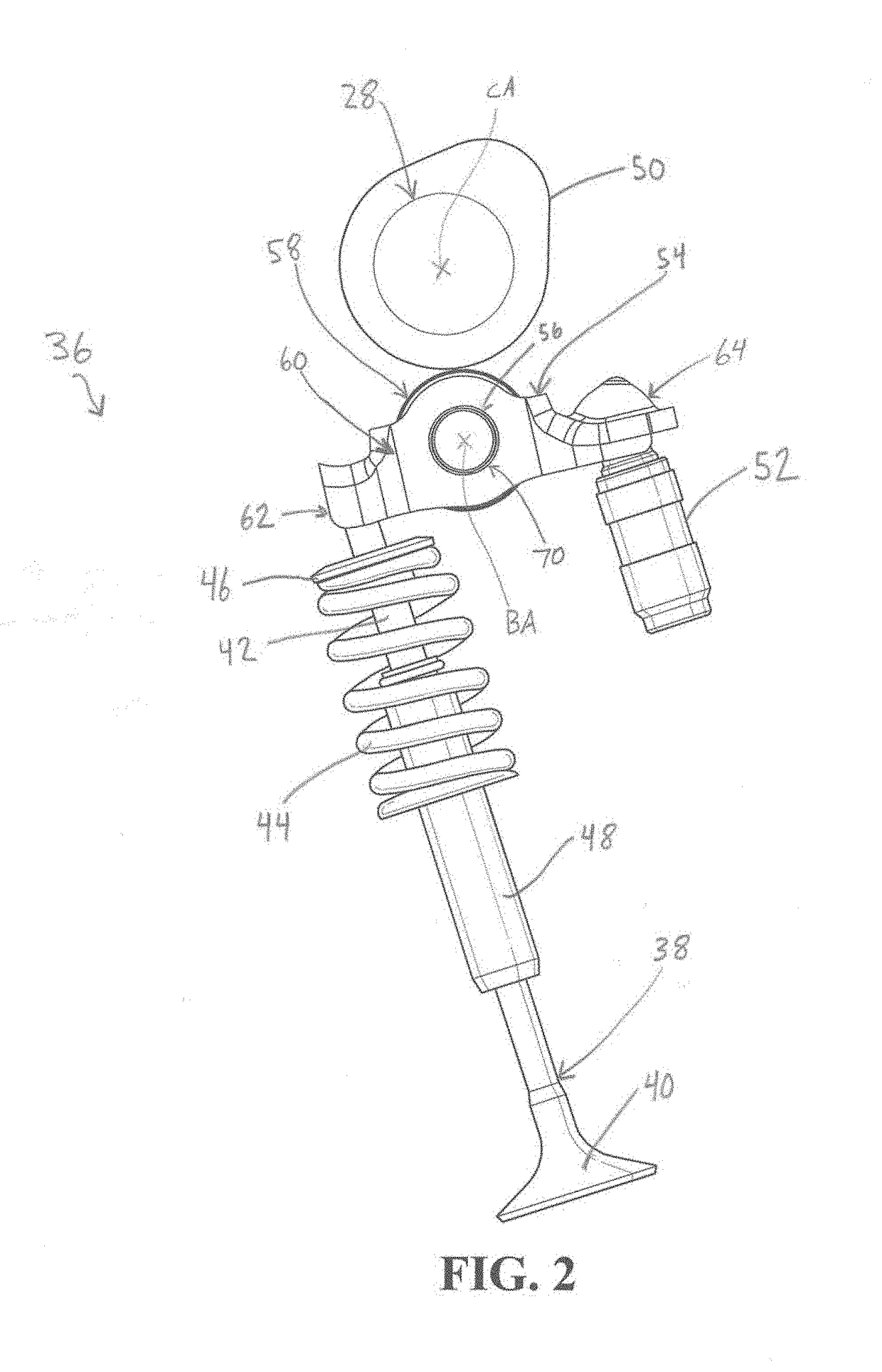
[0033]Reciprocal motion of the piston 32 generates rotational torque that is subsequently translated by the crankshaft 26 to the camshaft 28 which, i...


PUM


Abstract

A finger follower for use in an internal combustion engine valvetrain having a valve, a lash adjuster, and a camshaft having a lobe. The finger follower includes a shaft, a bearing rotatably supported by the shaft for engaging the lobe. A body is provided with a pad for engaging the valve, a socket spaced from the pad for engaging the lash adjuster, and walls disposed between the pad and the socket. A slot is formed in each wall for supporting the shaft, and each has a respective pair of eccentric arc-shaped bearing surfaces arranged to allow the shaft to rotate within the slots and to move along the slots to facilitate alignment of the bearing with respect to engagement with the lobe independent of alignment of the pad with respect to engagement with the valve and of alignment of the socket with respect to engagement with the lash adjuster.

Description

CROSS-REFERENCE TO RELATED APPLICATIONS[0001]The present application claims priority to and all the benefits of U.S. Provisional Patent Application No. 62 / 429,142, filed on Dec. 2, 2016, which is hereby expressly incorporated herein by reference in its entirety.BACKGROUND OF THE INVENTION1. Field of Invention[0002]The present invention relates, generally, to engine valvetrain systems and, more specifically, to a finger follower assembly for use in a valvetrain of a cylinder head of an internal combustion engine.2. Description of the Related Art[0003]Conventional engine valvetrain systems known in the art typically include one or more camshafts in rotational communication with a crankshaft supported in a block, one or more intake and exhaust valves supported in a cylinder head, and one or more intermediate members for translating radial movement from lobes of the camshaft into linear movement of the valves. The valves are used to regulate the flow of gasses in and out of cylinders of...

Claims


Application Information

Patent Timeline
Patent Type & Authority Applications(United States)
IPC IPC(8): F01L1/18F01L1/24
CPCF01L1/182F01L1/2416F01L1/181F01L2810/04F01L2810/03F01L1/185F01L2305/02F01L2305/00
Inventor BRUNE, JOHN EDMUNDSMITH, SCOTT PAUL
Owner GT TECH INC
Learn More